小学生
最后登录1970-1-1
在线时间 小时
注册时间2023-8-20
|
本帖最后由 13877159331 于 2023-8-22 14:49 编辑
一、主要原理
首先,上电后,利用RTC提供日历时间,并设置闹钟,在2.4寸液晶屏上实时显示,每个一个小时进行报时,三个LED都开启,此为正常模式。

接着,由于开启了低功耗模式的深度软件待机模式,按下开发板上的SW2键进入低功耗模式,三个LED关闭,屏幕熄灭,报时也会关闭。
然后,在低功耗模式下,如果按下SW2键,红灯闪10下,进入正常模式,显示一下时间,随后又进去低功耗模式;如果按下SW3键,红灯闪10下,进入正常模式。
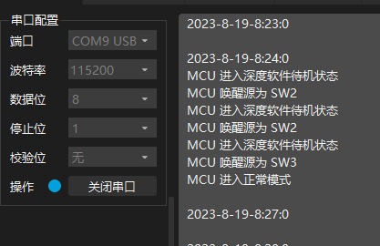
最后,由于开启串口4,我们可以从串口调试助手看到RA6M5的运行状况!
二、相关配置说明
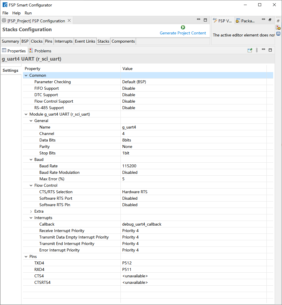
1.Uart4
2.RTC

3.深度软件待机模式
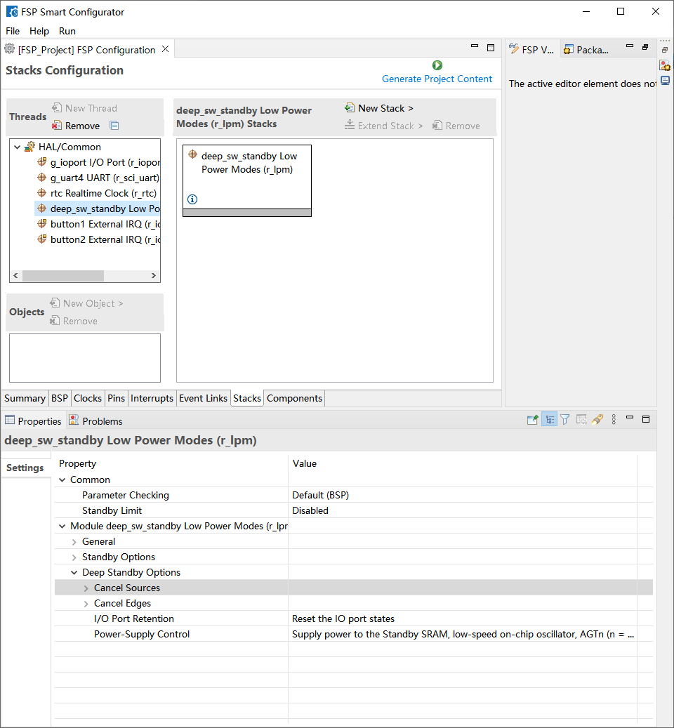
Cancel Sources 中开启IRQ9,IRQ10
4.按键外部中断
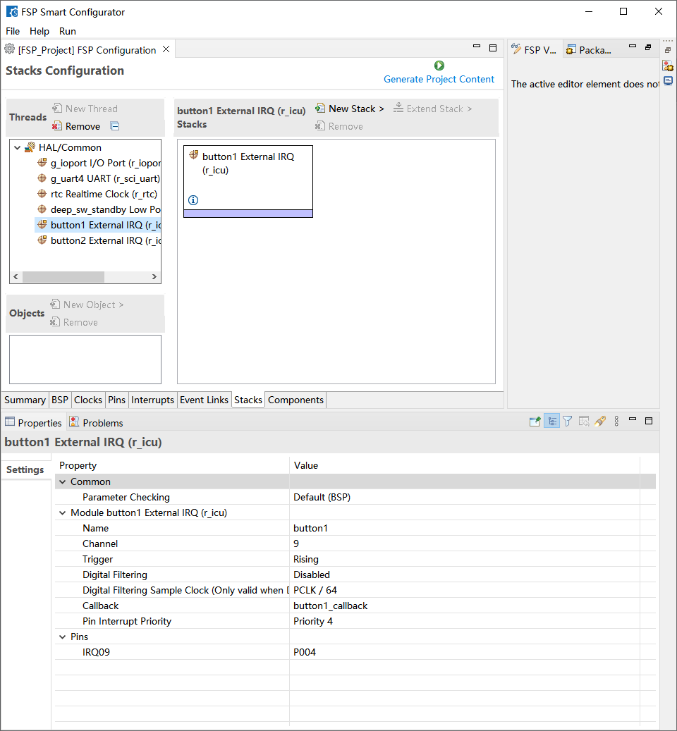
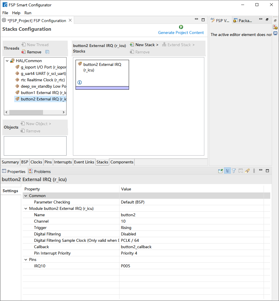
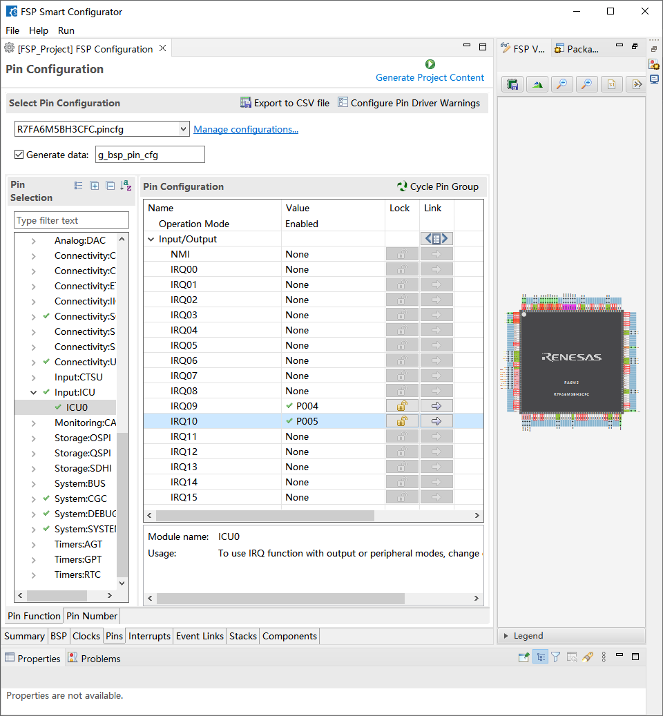
开启SW2和SW3的外部中断
5. 2.4寸液晶屏
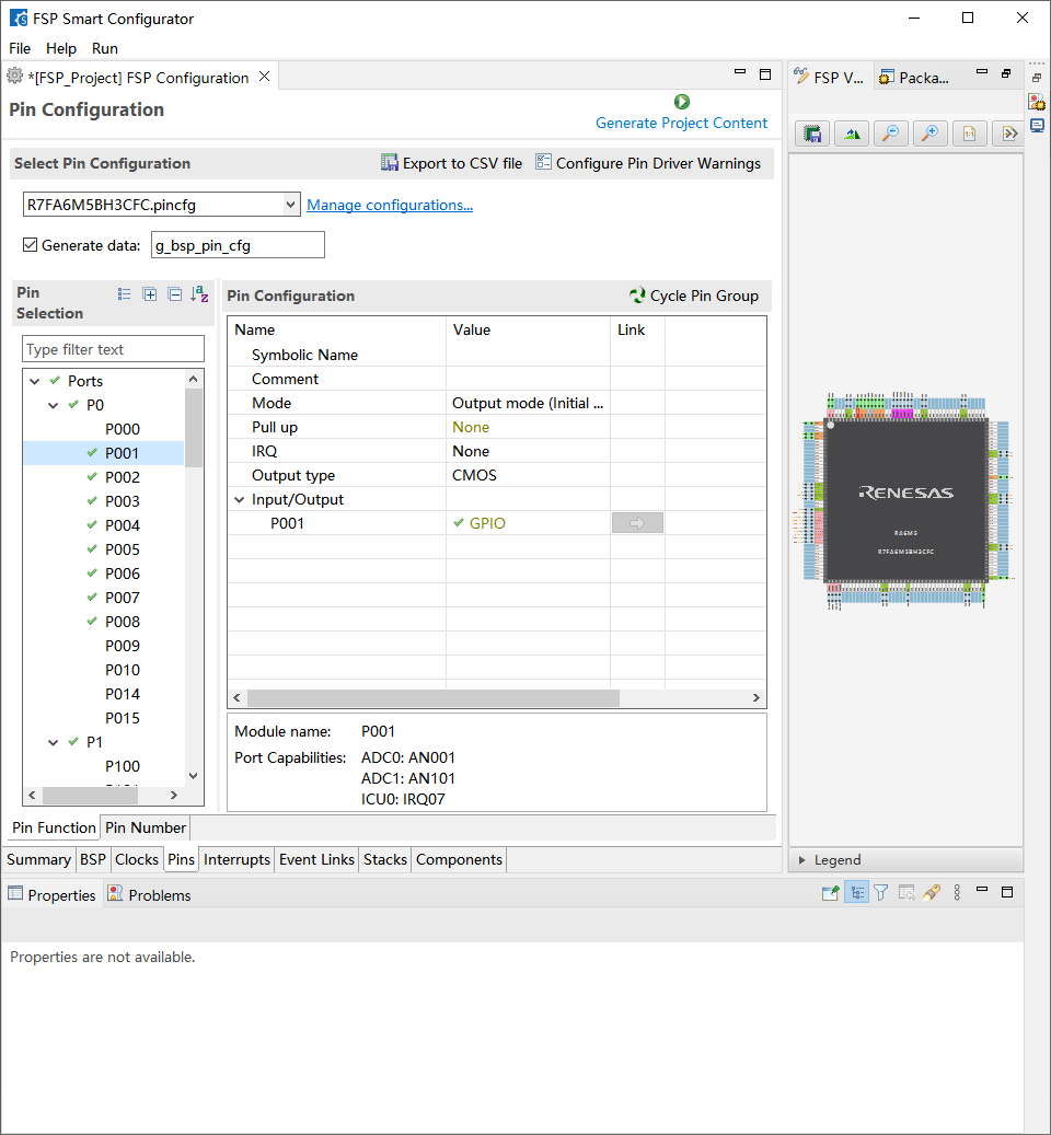
八个引脚P001~P003、P006~P008引脚配值为输出模式,模拟SPI进行驱动
三、相关代码(keil开发)
整体代码框架如图
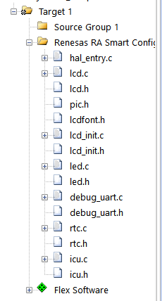
显示屏移植主要修改一下部分,延时更换一下差不多就可以了
- //-----------------LCD端口定义----------------
- #define LCD_MOSI_Set() R_IOPORT_PinWrite(&g_ioport_ctrl, BSP_IO_PORT_00_PIN_02, BSP_IO_LEVEL_HIGH)//SDA=MOST
- #define LCD_MOSI_Clr() R_IOPORT_PinWrite(&g_ioport_ctrl, BSP_IO_PORT_00_PIN_02, BSP_IO_LEVEL_LOW)
-
- #define LCD_SCLK_Set() R_IOPORT_PinWrite(&g_ioport_ctrl, BSP_IO_PORT_00_PIN_01, BSP_IO_LEVEL_HIGH)//SCL
- #define LCD_SCLK_Clr() R_IOPORT_PinWrite(&g_ioport_ctrl, BSP_IO_PORT_00_PIN_01, BSP_IO_LEVEL_LOW)
- #define LCD_RES_Set() R_IOPORT_PinWrite(&g_ioport_ctrl, BSP_IO_PORT_00_PIN_03, BSP_IO_LEVEL_HIGH)//(GPIOB,OLED_RST)
- #define LCD_RES_Clr() R_IOPORT_PinWrite(&g_ioport_ctrl, BSP_IO_PORT_00_PIN_03, BSP_IO_LEVEL_LOW)//(GPIOB,OLED_RST)
- #define LCD_DC_Set() R_IOPORT_PinWrite(&g_ioport_ctrl, BSP_IO_PORT_00_PIN_06, BSP_IO_LEVEL_HIGH)//(GPIOB,OLED_DC)
- #define LCD_DC_Clr() R_IOPORT_PinWrite(&g_ioport_ctrl, BSP_IO_PORT_00_PIN_06, BSP_IO_LEVEL_LOW)//(GPIOB,OLED_DC)
- #define LCD_CS_Set() R_IOPORT_PinWrite(&g_ioport_ctrl, BSP_IO_PORT_00_PIN_07, BSP_IO_LEVEL_HIGH)//(GPIOB,OLED_CS)
- #define LCD_CS_Clr() R_IOPORT_PinWrite(&g_ioport_ctrl, BSP_IO_PORT_00_PIN_07, BSP_IO_LEVEL_LOW)//(GPIOB,OLED_CS)
- #define LCD_BLK_Set() R_IOPORT_PinWrite(&g_ioport_ctrl, BSP_IO_PORT_00_PIN_08, BSP_IO_LEVEL_HIGH)//(GPIOB,OLED_RST)
- #define LCD_BLK_Clr() R_IOPORT_PinWrite(&g_ioport_ctrl, BSP_IO_PORT_00_PIN_08, BSP_IO_LEVEL_LOW)//(GPIOB,OLED_RST)
- //#define LCD_SCLK_Clr() GPIO_ResetBits(GPIOA,GPIO_Pin_5)//SCL=SCLK PA5
- //#define LCD_SCLK_Set() GPIO_SetBits(GPIOA,GPIO_Pin_5)
- //#define LCD_MOSI_Clr() GPIO_ResetBits(GPIOA,GPIO_Pin_7)//SDA=MOSI PA7
- //#define LCD_MOSI_Set() GPIO_SetBits(GPIOA,GPIO_Pin_7)
- //#define LCD_RES_Clr() GPIO_ResetBits(GPIOD,GPIO_Pin_2)//RES PD2
- //#define LCD_RES_Set() GPIO_SetBits(GPIOD,GPIO_Pin_2)
- //#define LCD_DC_Clr() GPIO_ResetBits(GPIOB,GPIO_Pin_5)//DC PB5
- //#define LCD_DC_Set() GPIO_SetBits(GPIOB,GPIO_Pin_5)
- //
- //#define LCD_CS_Clr() GPIO_ResetBits(GPIOA,GPIO_Pin_4)//CS PA4
- //#define LCD_CS_Set() GPIO_SetBits(GPIOA,GPIO_Pin_4)
- //#define LCD_BLK_Clr() GPIO_ResetBits(GPIOB,GPIO_Pin_6)//BLK PB6
- //#define LCD_BLK_Set() GPIO_SetBits(GPIOB,GPIO_Pin_6)
rtc.c代码
- #include "rtc.h"
- #include "led.h"
- #include "debug_uart.h"
- #include <stdio.h>
- uint16_t rtc_year =2023; //年
- uint8_t rtc_month =8; //月
- uint8_t rtc_day =8; //日
- uint8_t rtc_hour =23; //时
- uint8_t rtc_minute =59; //分
- uint8_t rtc_second= 53; //秒
- /********** 日期宏定义 **********/
- #define RTC_YEAR_SET 2023 //年
- #define RTC_MON_SET 8 //月
- #define RTC_MDAY_SET 18 //日
- /* 通过蔡勒公式计算星期 */
- #define RTC_WDAY_SET (RTC_YEAR_SET-2000 + ((RTC_YEAR_SET-2000)/4) - 35 + (26*(RTC_MON_SET+1))/10 + RTC_MDAY_SET -1 )%7
- #define RTC_HOUR_SET 23 //时
- #define RTC_MIN_SET 59 //分
- #define RTC_SEC_SET 48 //秒
- /************** 闹钟宏定义 **************/
- #define RTC_ALARM_YEAR_SET 2008 //年
- #define RTC_ALARM_MON_SET 8 //月
- #define RTC_ALARM_MDAY_SET 8 //日
- /* 通过蔡勒公式计算星期 */
- #define RTC_ALARM_WDAY_SET (RTC_YEAR_SET-2000+ ((RTC_YEAR_SET-2000)/4)- 35 + (26*(RTC_MON_SET+1))/10 + RTC_MDAY_SET -1 )%7
- #define RTC_ALARM_SEC_SET 00 //秒
- #define RTC_ALARM_MIN_SET 0 //分
- #define RTC_ALARM_HOUR_SET 0 //时
- /*** 使能闹钟比较 ***/
- #define RTC_ALARM_YEAR_ENABLE 0 //年
- #define RTC_ALARM_MON_ENABLE 0 //月
- #define RTC_ALARM_MDAY_ENABLE 0 //日
- #define RTC_ALARM_WDAY_ENABLE 0 //星期
- #define RTC_ALARM_SEC_ENABLE 0 //秒
- #define RTC_ALARM_MIN_ENABLE 1 //分
- #define RTC_ALARM_HOUR_ENABLE 0 //时
- void RTC_Init(void)
- {
- //初始化时设定的时间
- rtc_time_t set_time =
- { .tm_sec = RTC_SEC_SET, //秒
- .tm_min = RTC_MIN_SET, //分
- .tm_hour = RTC_HOUR_SET, //小时
- .tm_mday = RTC_MDAY_SET, //日(一个月中)
- .tm_wday = RTC_WDAY_SET, //星期
- .tm_mon = RTC_MON_SET, //月份
- .tm_year = RTC_YEAR_SET-1900, //年份(如今年是 2008,则这里输入 2008-1900=108)
- };
-
- /* 打开 RTC 模块 */
- R_RTC_Open (rtc.p_ctrl, rtc.p_cfg);
-
- /* 时钟源设置,如果在 FSP Configuration 设置"Set Source Clock in Open" 为"enabled",那这一步可以被跳过 */
- R_RTC_ClockSourceSet (rtc.p_ctrl);
-
- /* 若 RTC 时钟已经使用纽扣电池工作了一段时间,则可以使用这个函数获取当前日历并设置当前时间 */
- R_RTC_CalendarTimeGet(rtc.p_ctrl,&set_time);
-
- /* 这个函数至少调用一次以启动 RTC*/
- R_RTC_CalendarTimeSet (rtc.p_ctrl, &set_time); //设置当前时间
-
- /* 设置周期中断的周期为 1 秒 */
- //R_RTC_PeriodicIrqRateSet (rtc.p_ctrl, RTC_PERIODIC_IRQ_SELECT_1_SECOND);
- }
- void RTC_Alarm_Init(void)
- {
- rtc_alarm_time_t alarm_time =
- {
- .time = {
- .tm_sec = RTC_ALARM_SEC_SET, //秒
- .tm_min = RTC_ALARM_MIN_SET, //分
- .tm_hour = RTC_ALARM_HOUR_SET, //小时
- .tm_mday = RTC_ALARM_MDAY_SET, //日(一个月中)
- .tm_wday = RTC_ALARM_WDAY_SET, //星期
- .tm_mon = RTC_ALARM_MON_SET, //月份
- .tm_year = RTC_ALARM_YEAR_SET-1900, //年份
- },
- .dayofweek_match = RTC_ALARM_WDAY_ENABLE,
- .hour_match = RTC_ALARM_HOUR_ENABLE,
- .mday_match = RTC_ALARM_MDAY_ENABLE,
- .min_match = RTC_ALARM_MIN_ENABLE,
- .mon_match = RTC_ALARM_MON_ENABLE,
- .sec_match = RTC_ALARM_SEC_ENABLE,
- .year_match = RTC_ALARM_YEAR_ENABLE,
- };
- R_RTC_CalendarAlarmSet(rtc.p_ctrl, &alarm_time);
- }
- void Buzzer_sout()
- {
- R_IOPORT_PinWrite(&g_ioport_ctrl, BSP_IO_PORT_06_PIN_05, BSP_IO_LEVEL_HIGH);
- R_BSP_SoftwareDelay(100, BSP_DELAY_UNITS_MILLISECONDS); //Delay 120ms
- R_IOPORT_PinWrite(&g_ioport_ctrl, BSP_IO_PORT_06_PIN_05, BSP_IO_LEVEL_LOW);
- }
- void rtc_callback(rtc_callback_args_t *p_args)
- {
- static rtc_time_t get_time;
- switch (p_args->event)
- {
- /* 若是周期中断,则发送日期给串口并切换 LED 电平 */
- case RTC_EVENT_PERIODIC_IRQ:
-
- break;
-
- case RTC_EVENT_ALARM_IRQ:
- /* 获取当前时间 */
- R_RTC_CalendarTimeGet (rtc.p_ctrl, &get_time);
-
- /* 打印当前时间 */
- printf("\r\n%d-%d-%d-%d:%d:%d\r\n", get_time.tm_year + 1900,get_time.tm_mon, get_time.tm_mday,get_time.tm_hour, get_time.tm_min, get_time.tm_sec);
- Buzzer_sout(); //蜂鸣器叫一声
- break;
- default:
- break;
- }
- }
- void Gettime(void)
- {
- R_RTC_CalendarTimeGet (rtc.p_ctrl, &get_time);
- rtc_second=get_time.tm_sec; //获取秒
- rtc_minute=get_time.tm_min; //获取分
- rtc_hour=get_time.tm_hour; //获取时
- rtc_day=get_time.tm_mday; //获取日
- rtc_month=get_time.tm_mon; //获取月
- rtc_year=get_time.tm_year+1900; //获取年
- }
- #include "hal_data.h"
- #include "led.h"
- #include "debug_uart.h"
- #include <stdio.h>
- #include "lcd_init.h"
- #include "lcd.h"
- #include "pic.h"
- #include "rtc.h"
- #include "icu.h"
- FSP_CPP_HEADER
- void R_BSP_WarmStart(bsp_warm_start_event_t event);
- FSP_CPP_FOOTER
- /*******************************************************************************************************************//**
- * main() is generated by the RA Configuration editor and is used to generate threads if an RTOS is used. This function
- * is called by main() when no RTOS is used.
- **********************************************************************************************************************/
- void hal_entry(void)
- {
- /* TODO: add your own code here */
- R_BSP_PinAccessEnable(); //启用对 PFS 寄存器的访问, 因为后面写 IO 口都用 BSP 内联函数
- LED_Init(); // LED 初始化
- Debug_UART4_Init(); // SCI4 UART 调试串口初始化
- IRQ_Init();
-
- RTC_Init(); //初始化 RTCLCD_Init();//LCD初始化
- RTC_Alarm_Init(); //初始化闹钟
-
- /* 判断是否在深度软件待机模式下被唤醒 */
- if (1U == R_SYSTEM->RSTSR0_b.DPSRSTF)
- {
- /* 从深度软件待机模式唤醒后清除 IOkeep 位,以允许使用 IO 端口 */
- R_LPM_IoKeepClear (NULL);
-
- /* 清除唤醒标志位 */
- R_SYSTEM->RSTSR0_b.DPSRSTF = 0;
-
- /* 判断唤醒源是 IRQ-9 还是 IRQ-10,并将判断结果打印出来 */
- if (R_SYSTEM->DPSIFR1 >> 1 & 0x01U)
- {
- printf("MCU 唤醒源为 SW2\r\n");
- }
- else if (R_SYSTEM->DPSIFR1 >> 2 & 0x01U)
- {
- printf("MCU 唤醒源为 SW3\r\n");
- printf("MCU 进入正常模式\r\n");
- }
- }
- LED_Flicker (10); //LED 闪烁 10 次
-
- LCD_Init();
- LCD_Fill(0,0,LCD_W,LCD_H,WHITE);
- LCD_ShowChinese(49 +40 , 97, "年",DARKBLUE,WHITE,24,0);
- LCD_ShowChinese(97 +40 , 97, "月",DARKBLUE,WHITE,24,0);
- LCD_ShowChinese(145+40 ,97, "日",DARKBLUE,WHITE,24,0);
-
- LCD_ShowChinese(25 +40, 73,"时",DARKBLUE,WHITE,24,0);
- LCD_ShowChinese(73 +40, 73,"分",DARKBLUE,WHITE,24,0);
- LCD_ShowChinese(121+40, 73,"秒",DARKBLUE,WHITE,24,0);
-
- while(1)
- {
- LED1_ON;
- LED2_ON;
- LED3_ON;
- Gettime();
- LCD_Backlight_On();
- LCD_ShowChinese(49, 0, "【野火】", DARKBLUE, WHITE, 24, 0);
- LCD_ShowString(150,0,"RA",DARKBLUE,WHITE, 24, 0);
- LCD_ShowString(36,25,"MCU",DARKBLUE,WHITE, 24, 0);
- LCD_ShowChinese(73, 25, "创意氛围赛", DARKBLUE, WHITE, 24, 0);
- LCD_ShowIntNum(0 +40, 97, rtc_year, 4, DARKBLUE, WHITE, 24);
- LCD_ShowIntNum(73 +40, 97, rtc_month, 2, DARKBLUE, WHITE, 24);
- LCD_ShowIntNum(121+40, 97, rtc_day, 2, DARKBLUE, WHITE, 24);
-
- LCD_ShowIntNum(0 +40 , 73, rtc_hour, 2, DARKBLUE, WHITE, 24);
- LCD_ShowIntNum(49+40 , 73, rtc_minute, 2, DARKBLUE,WHITE, 24);
- LCD_ShowIntNum(97+40 , 73, rtc_second, 2, DARKBLUE,WHITE, 24);
-
- LCD_ShowChinese(49, 145, "当前模式", DARKBLUE, WHITE, 16, 0);
- LCD_ShowString(113, 145, ":",DARKBLUE,WHITE, 16, 0);
- LCD_ShowChinese(120, 145, "正常模式", DARKBLUE, WHITE, 16, 0);
-
- LCD_ShowChinese(0, 217-48, "正常模式按", DARKBLUE, WHITE, 16, 0);
- LCD_ShowString(82, 217-48,"SW2",DARKBLUE,WHITE, 16, 0);
- LCD_ShowChinese(108,217-48, "键进入低功耗模式", DARKBLUE, WHITE, 16, 0);
-
- LCD_ShowChinese(0, 240-48, "低功耗模式按", DARKBLUE, WHITE, 16, 0);
- LCD_ShowString(98, 240-48,"SW2",DARKBLUE,WHITE, 16, 0);
- LCD_ShowChinese(124,240-48, "键进入正常模式", DARKBLUE, WHITE, 16, 0);
-
- LCD_ShowChinese(82, 256-48, "按", DARKBLUE, WHITE, 16, 0);
- LCD_ShowString(98, 256-48,"SW3",DARKBLUE,WHITE, 16, 0);
- LCD_ShowChinese(124,256-48, "键进入正常模式", DARKBLUE, WHITE, 16, 0);
- LCD_ShowChinese(49, 272-48, "随后又进入低功耗模式", DARKBLUE, WHITE, 16, 0);
-
- LCD_ShowPicture(0,260,100,49,gImage_1);
- LCD_ShowPicture(138,262,100,44,gImage_2);
-
- R_BSP_SoftwareDelay(800, BSP_DELAY_UNITS_MILLISECONDS);
- if (key_flag == true)
- {
- /* 标志位置 0,防止程序不断进入 if 的代码块里面 */
- key_flag = false;
-
- /*LED 闪烁 2 次 */
- LED_Flicker (2);
- LED1_OFF;
- LED2_OFF;
- LED3_OFF;
-
- LCD_Backlight_Off();
- LCD_Fill(0,0,LCD_W,LCD_H,WHITE);
- LCD_ShowChinese(73, 110, "唤醒中", RED, WHITE, 24, 0);
-
- /* 进入低功耗模式前打印 */
- printf("MCU 进入深度软件待机状态\r\n");
-
- /* 打开 LPM, 进入深度软件待机状态 */
- R_LPM_Open (deep_sw_standby.p_ctrl, deep_sw_standby.p_cfg);
- R_LPM_LowPowerModeEnter (deep_sw_standby.p_ctrl);
-
- /* 唤醒后打印,但是在进入深度软件待机模式后不能保存上下文,
- 故这里正常来说无法被执行, 如果执行了则说明进入的是睡眠模式,
- 也就是程序出现了问题,一般刚烧写程序会导致这个问题,重新上电即可恢复正常 */
- printf("MCU 被唤醒(出现本消息说明程序出错)\r\n");
- }
-
- }
- #if BSP_TZ_SECURE_BUILD
- /* Enter non-secure code */
- R_BSP_NonSecureEnter();
- #endif
- }
- /*******************************************************************************************************************//**
- * This function is called at various points during the startup process. This implementation uses the event that is
- * called right before main() to set up the pins.
- *
- * @param[in] event Where at in the start up process the code is currently at
- **********************************************************************************************************************/
- void R_BSP_WarmStart (bsp_warm_start_event_t event)
- {
- if (BSP_WARM_START_RESET == event)
- {
- #if BSP_FEATURE_FLASH_LP_VERSION != 0
- /* Enable reading from data flash. */
- R_FACI_LP->DFLCTL = 1U;
- /* Would normally have to wait tDSTOP(6us) for data flash recovery. Placing the enable here, before clock and
- * C runtime initialization, should negate the need for a delay since the initialization will typically take more than 6us. */
- #endif
- }
- if (BSP_WARM_START_POST_C == event)
- {
- /* C runtime environment and system clocks are setup. */
- /* Configure pins. */
- R_IOPORT_Open(&g_ioport_ctrl, g_ioport.p_cfg);
- }
- }
- #if BSP_TZ_SECURE_BUILD
- BSP_CMSE_NONSECURE_ENTRY void template_nonsecure_callable ();
- /* Trustzone Secure Projects require at least one nonsecure callable function in order to build (Remove this if it is not required to build). */
- BSP_CMSE_NONSECURE_ENTRY void template_nonsecure_callable ()
- {
- }
- #endif
四、遇到的问题及总结
1.我们使用keil开发RA6M5时可以用stlink下载,也可以使用Debug调试,有时候下载程序进去后,点Dubug出错,可以先编译,然后直接进去Debug,它下载好然后进去!
2.RTC时钟源可以选择子时钟或LOCO,按照FSP库实战指南时钟源选择Sub-Clock,小时进位到时,进位不了,改为LOCO,就可以了,其他配置都一样,不懂为什么,有大佬知道的话,欢迎评论区留言!
3.低功耗模式配置为深度软件待机模式,用stlink下载进去后,程序有点错乱,就是什么中断都可以唤醒MCU,复位之后也不行,但在深度软件待机模式下,下载程序,下载不了,然后程序就神奇的变好了,同上,欢迎大佬留言!
4.由于参加电赛不怎么够时间完成作品,打算用esp8266联网获取准确时间,做不出来(基础不好),最后感谢野火举办的瑞萨RA MCU创意氛围赛,让我有机会学习到相关的内容!!!
五、相关链接
1.视频:https://www.bilibili.com/video/BV1Tw41197j7/?spm_id_from=333.999.0.0&vd_source=e567d33338fa6c85ccc0dc7586dca675
2.代码见附件! |
|