|
前言 板子拿到手已经一周了,看着官方文档研究了一番,发现启明R6M5的板载资源是真的丰富,各种外设俱全,考虑的很周到,而瑞萨的配套资源用起来也是相当的丝滑。介于这款板子网上资料丰富,就不写开箱贴了,直接上手试验一下使用PWM驱动LED。 1. 准备工作如果手头有JLINK V9级以上版本,可以使用E2studio开发,e2studio是基于eclipse二次开发的,使用起来还是相当的方便。 由于本人缺少JLINK,所以采用KEIL5来开发,调试器使用的十几块钱的STLINK V2。 开发环境: - 电脑:Win10
- IDE:KEIL V5.34
- 配置软件:RASC V4.0.0
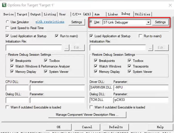
使用STLINK下载配置如下图:
 关于如何创建一个KEIL工程,可以直接参考野火提供的参考资料( 点此链接查看教程),本文不做赘述。 直接讲解如何配置GPIO口为PWM。 2.1 端口复用信息打开启明RA6M5的原理图,查看LED线路连接: - LED1 --> P400
- LED2 --> P403
- LED3 --> P404
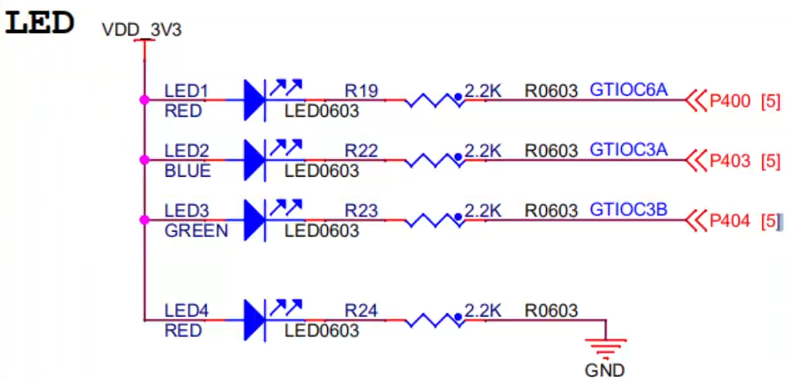
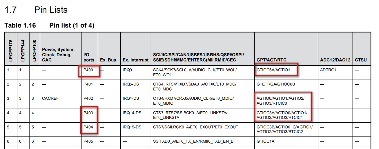
打开数据手册查看这三个引脚连接的GPT端口: - P400 --> GTIOC6A(GPT6A)
- P403 --> GTIOC3A(GPT3A)
- P404 --> GTIOC3B(GPT3B)
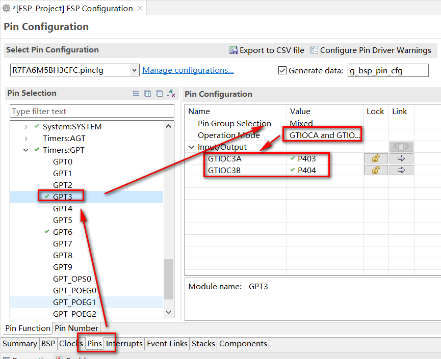
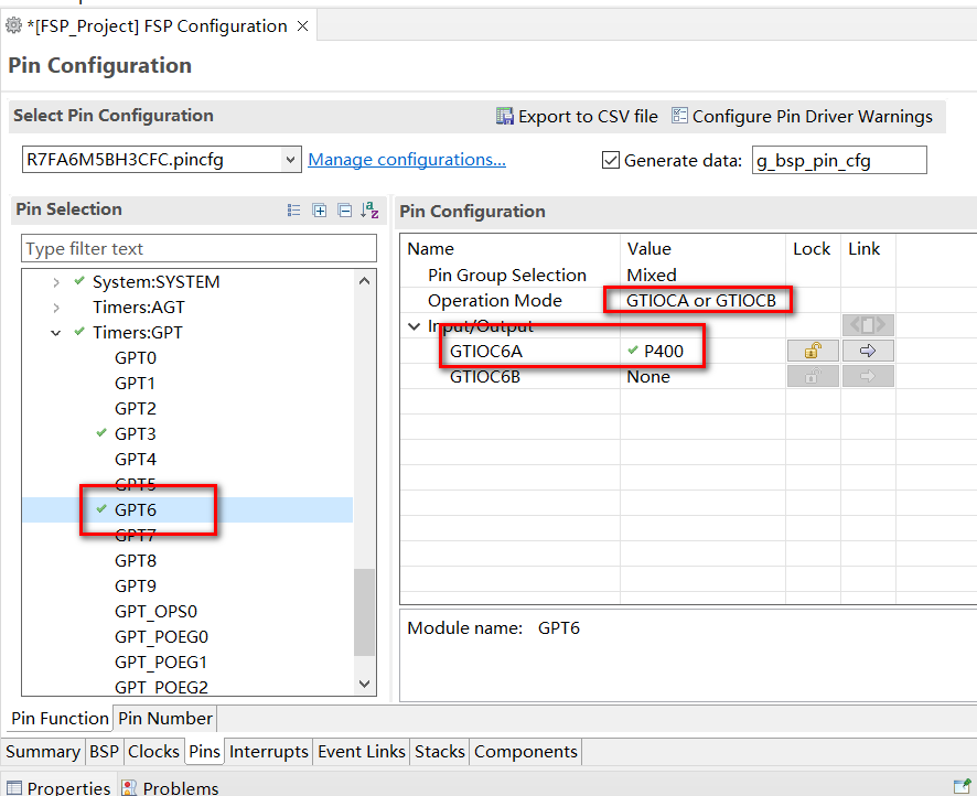
2.2 RASC配置打开RASC配置相应的端口。 如下,需要使能GPT3和GPT6,根据复用信息配置即可。 在Pin配置页面下配置如下信息:
 在stack下配置PWM:
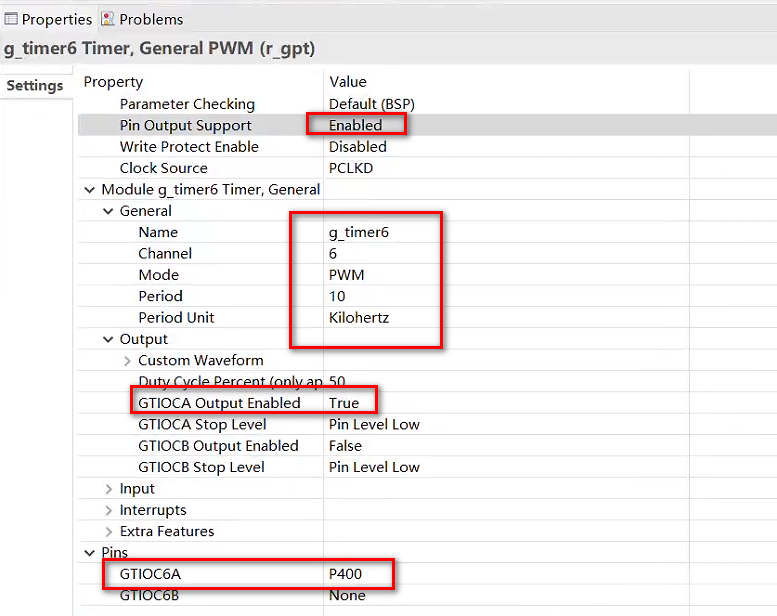
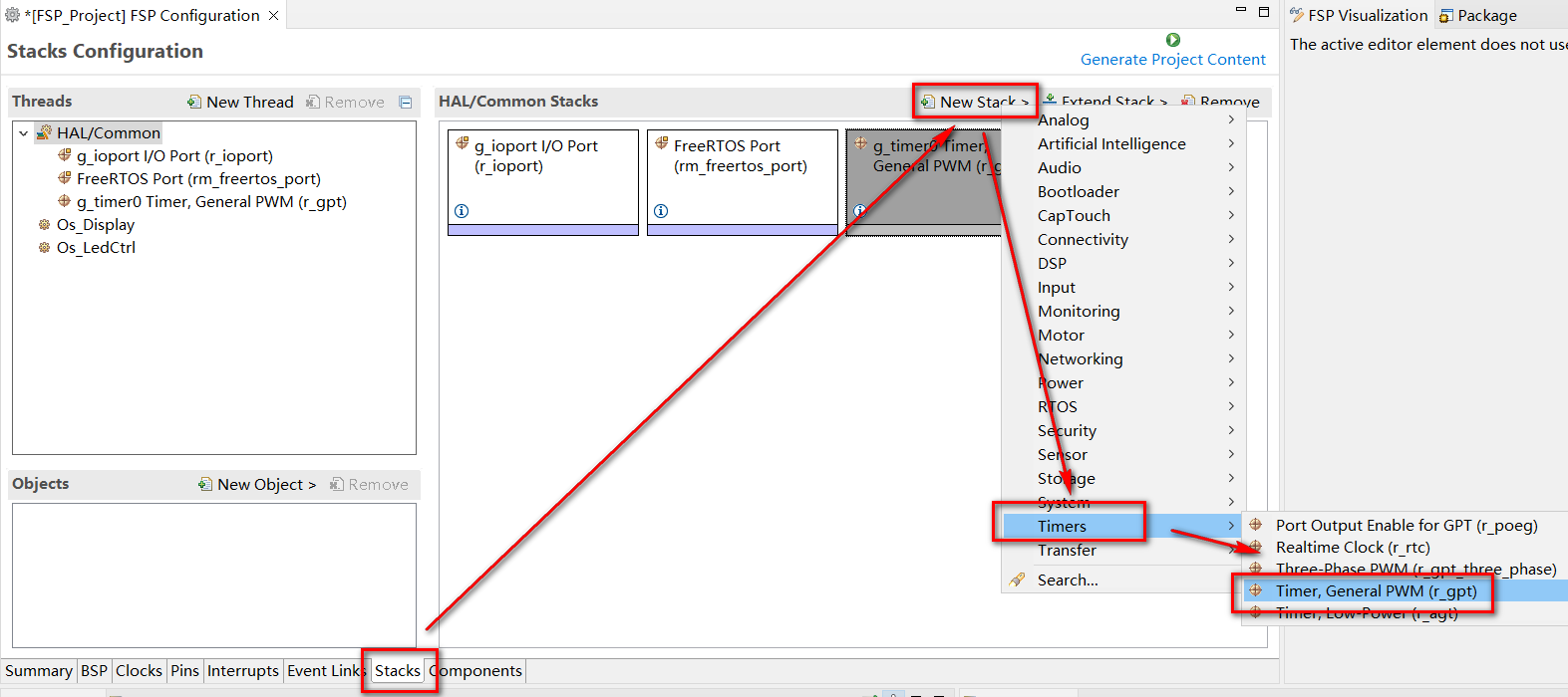 下图以P400配置为例,配置使能GPT6A,如下:
 代码上是集成了GPIO控制的逻辑: app_led.c - /*
- @hehung
- 2023-5-22
- email: 1398660197@qq.com
- wechat: hehung95
- reproduced and please indicate the source @hehung
- */
- #include "hal_data.h"
- #include "app_led.h"
- #define LED_DEBUG
- #undef LED_DEBUG
- #ifdef LED_DEBUG
- #include <stdio.h>
- #endif
- #if (LED_CTRL_TYPE == LED_CTRL_METHOD_IO)
- #define LED_ON (BSP_IO_LEVEL_HIGH)
- #define LED_OFF (BSP_IO_LEVEL_LOW)
- static bsp_io_port_pin_t led_pin[LED_TOTAL_NUM] =
- {
- BSP_IO_PORT_04_PIN_00, /* LED1 */
- BSP_IO_PORT_04_PIN_03, /* LED2 */
- BSP_IO_PORT_04_PIN_04 /* LED3 */
- };
- #endif
- #if (LED_CTRL_TYPE == LED_CTRL_METHOD_IO)
- void Led_Ctrl(uint8_t led_num, uint8_t led_level)
- {
- (void)R_IOPORT_PinWrite(&g_ioport_ctrl, led_pin[led_num], (bsp_io_level_t)led_level);
- }
- #endif
- void Led_Init(void)
- {
- #if (LED_CTRL_TYPE == LED_CTRL_METHOD_PWM)
- /* Initialize Gpt6 */
- (void)R_GPT_Open(&g_timer6_ctrl, &g_timer6_cfg);
- /* Enable Gpt6 */
- (void)R_GPT_Enable(&g_timer6_ctrl);
- /* Start Gpt6 */
- (void)R_GPT_Start(&g_timer6_ctrl);
- /* Initialize Gpt3 */
- (void)R_GPT_Open(&g_timer3_ctrl, &g_timer3_cfg);
- /* Enable Gpt3 */
- (void)R_GPT_Enable(&g_timer3_ctrl);
- /* Start Gpt3 */
- (void)R_GPT_Start(&g_timer3_ctrl);
- /* setting the frequency */
- R_GPT_PeriodSet(&g_timer6_ctrl, 10000); // frequency
- /* setting the frequency */
- R_GPT_PeriodSet(&g_timer3_ctrl, 10000); // frequency
- #endif
- }
- void Led_Running(void)
- {
- #if (LED_CTRL_TYPE == LED_CTRL_METHOD_IO)
- static uint8_t i = 0;
- static uint8_t flag = 0;
- Led_Ctrl(i, flag);
- i = (i < LED_TOTAL_NUM) ? (i+1) : (0);
- if (i == 0)
- {
- flag ^= 1;
- }
- #elif (LED_CTRL_TYPE == LED_CTRL_METHOD_PWM)
- fsp_err_t err = FSP_SUCCESS;
- static uint16_t duty_cycle = 0;
- duty_cycle = (duty_cycle < 10000) ? (duty_cycle + 100) : (0);
- err = R_GPT_DutyCycleSet(&g_timer6_ctrl, duty_cycle, GPT_IO_PIN_GTIOCA);// duty cycle
- assert(FSP_SUCCESS == err);
- err = R_GPT_DutyCycleSet(&g_timer3_ctrl, duty_cycle, GPT_IO_PIN_GTIOCA);// duty cycle
- assert(FSP_SUCCESS == err);
- err = R_GPT_DutyCycleSet(&g_timer3_ctrl, duty_cycle, GPT_IO_PIN_GTIOCB);// duty cycle
- assert(FSP_SUCCESS == err);
- #endif
- }
app_led.h - /*
- @hehung
- 2023-5-22
- email: 1398660197@qq.com
- wechat: hehung95
- reproduced and please indicate the source @hehung
- */
- #ifndef APP_LED_H_
- #define APP_LED_H_
- #include "hal_data.h"
- #define LED_CTRL_METHOD_PWM (1U)
- #define LED_CTRL_METHOD_IO (0U)
- #define LED_CTRL_TYPE (LED_CTRL_METHOD_PWM)
- // Total number of leds
- #define LED_TOTAL_NUM (3U)
- #define LED_3 (2U)
- #define LED_2 (1U)
- #define LED_1 (0U)
- extern void Led_Init(void);
- extern void Led_Ctrl(uint8_t led_num, uint8_t led_level);
- extern void Led_Running(void);
- #endif /* APP_LED_H_ */
主函数逻辑如下: - Led_Init();
- while(1)
- {
- Led_Running();
- }
3. 试验效果
| 


 发表于 2023-5-26 10:29:13

 提升卡
提升卡