本帖最后由 GCT 于 2022-7-15 16:33 编辑
入门第九课《自己写库—构建库函数雏形》课后作业汇总 入门篇 第九课内所有题目: 9.1

9.3

使用新的库函数的方案继续优化之前的led灯闪烁程序

目标:简化宏定义部分。如果对于每个外设都去写对于基地址物理地址的宏定义,要去写指针还要去翻参考手册,会特别麻烦。 看过参考手册可以对外设总结出一个共性:所有的寄存器都占用32byte,而且地址连续排列。有没有一种方式能替换这些宏定义? C语言有一种结构叫做结构体,它包含的数据成员可以是不同类型的,最重要的是,它的物理地址是对齐的连续排列的。
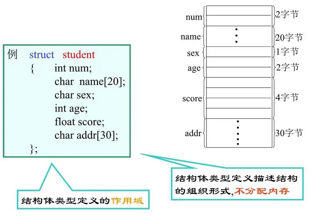
结构体的存放特性恰好迎合了我们对于外设寄存器的需求:大小相同,连续排列 可以将上面的宏定义修改成结构体的定义: 首先先定义两个新的类型:uint32_t和uint16_t。uint16_t用来定义16bit类型,c语言的short类型恰好大小为2byte; uint32_t用来定义32bit类型,c语言的int类型恰好大小为4byte。取个别名应该是为了统一便于编程,u代表unsigned,就不需要写那么多遍unsigned了。

RCC时钟的寄存器如下:
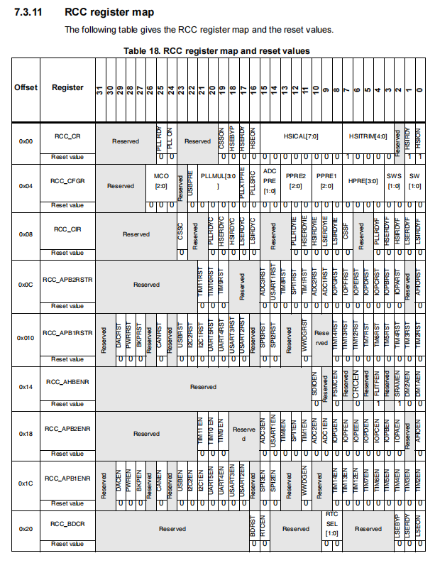

结构体定义如下:


注意:不管是否要用到,必须写上所有的寄存器!一定要写全!因为地址是连续的,如果不写的话寄存器对应的地址就错了! 定义完结构体以后需要告诉程序定义的结构体首地址应该在哪里。RCC_BASE基地址之前已经定义好了,但是程序不知道这个是RCC外设的基地址。 使用c语言方法将这个地址(宏定义完还是立即数)强制转换为结构体RCC_TypeDef的指针,告诉它你是一个地址,应该指向结构体。
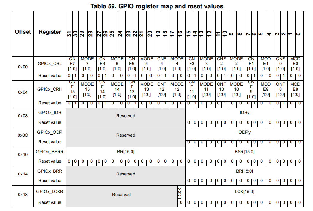
用相同的方法定义GPIO寄存器:

完整头文件stm32f10x.h代码如下: - #ifndef __STM32F10X_H
- #define __STM32F10X_H
- //用来存放STM32寄存器映射的代码
- //外设 peripheral
- #define PERIPH_BASE ((unsigned int)0x40000000)
- #define APB2PERIPH_BASE (PERIPH_BASE + 0x10000)
- #define AHBPERIPH_BASE (PERIPH_BASE + 0x20000)
- #define RCC_BASE (AHBPERIPH_BASE+0x1000)
- #define GPIOB_BASE (APB2PERIPH_BASE+0x0C00)
- typedef unsigned int uint32_t;
- typedef unsigned short uint16_t;
- typedef struct
- {
- uint32_t CR;
- uint32_t CFGR;
- uint32_t CIR;
- uint32_t APB2RSTR;
- uint32_t APB1RSTR;
- uint32_t AHBENR;
- uint32_t APB2ENR;
- uint32_t APB1ENR;
- uint32_t BDCR;
- uint32_t CSR;
- }RCC_TypeDef;
- #define RCC ((RCC_TypeDef*)RCC_BASE)
- typedef struct
- {
- uint32_t CRL;
- uint32_t CRH;
- uint32_t IDR;
- uint32_t ODR;
- uint32_t BSRR;
- uint32_t BRR;
- uint32_t LCKR;
- }GPIO_TypeDef;
- #define GPIOB ((GPIO_TypeDef*)GPIOB_BASE)
- #endif /*__STM32F10X_H*/
修改优化后的红蓝闪烁代码如下:
- #include "stm32f10x.h"
- #include "stm32f10x_gpio.h"
- #define Red 5
- #define Green 0
- #define Blue 1
- void delay_us(int delay_us);
- void delay_ms(int delay_ms);
- void initial(int clp);
- void ledBlink(int cl);
- int main(void)
- {
- RCC->APB2ENR |=(1<<3);
- while(1)
- {
- initial(Red);
- ledBlink(Red);
- initial(Blue);
- ledBlink(Blue);
- }
- }
- //函数体为空,目的是为了骗过编译器不报错
- void SystemInit(void)
- {}
- //微秒级的延时
- void delay_us(int delay_us)
- {
- volatile unsigned int num;
- volatile unsigned int t;
- for (num = 0; num < delay_us; num++)
- {
- t = 11;
- while (t != 0)
- {
- t--;
- }
- }
- }
- //毫秒级的延时
- void delay_ms(int delay_ms)
- {
- volatile unsigned int num;
- for (num = 0; num < delay_ms; num++)
- {
- delay_us(1000);
- }
- }
- void initial(int clp)
- {
- GPIOB->CRL &=~((0x0F)<<(4*clp));
- GPIOB->CRL |=(1<<(4*clp));
- }
- void ledBlink(int cl)
- {
- GPIOB->BSRR &=~(1<<cl);
- delay_ms(100);
- GPIOB->BRR &=~(1<<cl);
- GPIOB->CRL &=~((0x0F)<<(4*cl));
- }
目标:优化寄存器操作部分,使代码可读性增强。如果寄存器修改使用|=1<<(4*cl)这样的方法,对于其他开发人员如果没有注释和参考手册,很难理解要干什么。
而且,使用结构体以后,main.c并没有得到真正的优化,只是别名改了而已。
创建新的文件:stm32f10x_gpio.c,用来存放封装寄存器操作的函数;其对应的头文件stm32f10x_gpio.h,用来存放对于外设硬件方面的宏定义
(一般对于硬件有关的 直接进行宏定义)
在写头文件的宏定义之前,有一点规范是需要注意的。


当头文件一多以后,难免会出现相互引用的情况,这样编译就会报错说重复定义。
解决方法是每次写头文件的时候先写三句宏定义,再写别的定义:
#ifndef __<头文件名字 全大写>_H
#define __<头文件名字 全大写>_H
xxx(此处写其他定义)
#endif /*__<头文件名字 全大写>_H*/
也算是一种江湖规矩
有些定义和函数声明需要用到结构体定义,所以先要包含主头文件stm32f10x.h

我先对所有的GPIOA-GPIOG进行了定义,为的是方便进行时钟的设置。

然后定义了用于设置GPIO不同引脚模式的宏(后面课上讲了更好的方法——用枚举类型 灵活性好),这里所有口默认设置为推挽输出,10MHz

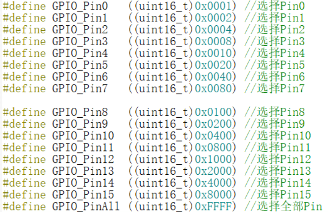
最后定义用于控制具体端口输入输出内容的宏:
下面先开始写函数部分,在stm32f10x_gpio.c
先包含它的专属头文件:stm32f10x_gpio.h
弄清需要那些功能:RCC时钟设置、清空CRL、CRL设置模式、位“置1”、位“清除”。
总体如下:

因为是模拟的库函数,有些名字是我自己起的,可能和库函数的不一致。
函数定义需要写到头文件,便于main.c调用
RCC时钟设置函数(RCC_Enable()):
参数:RCC寄存器地址,GPIO端口选哪一个
函数内容:相应RCC寄存器置1操作使能时钟,对应原来的RCC->APB2ENR |= (1<<3);

CRL清空函数(GPIO_ClearRL()):
函数内容:清空对应GPIO引脚的初始值或给定值,为的是让后续的按位或 置1操作能够顺利进行不出错(防止出现例如之前的按位或之后变成开漏输出的情况)。

CRL配置函数(GPIO_ConfigRL()):
函数内容:配置对应GPIO引脚为推挽输出、10MHz(设定成默认值,现在不能选择其他选项)

BSRR位设置函数(GPIO_SetBits()):
函数内容:配置对应GPIO引脚输出高电平(LED关)

BRR位设置函数(GPIO_ResetBits()):
函数内容:配置对应GPIO引脚输出低电平(LED开)

经过优化后的完整红蓝闪烁代码:
stm32f10x_gpio.c:
- #include "stm32f10x_gpio.h"
- void RCC_Enable(RCC_TypeDef *RCCx,uint16_t IOPortx)
- {
- RCCx->APB2ENR |=IOPortx;
- }
- void GPIO_ClearRL(GPIO_TypeDef *GPIOx,uint32_t GPIO_Pin)
- {
- GPIOx->CRL &=~GPIO_Pin;
- }
- void GPIO_ConfigRL(GPIO_TypeDef *GPIOx,uint32_t GPIO_Pin)
- {
- GPIOx->CRL |=GPIO_Pin;
- }
- void GPIO_SetBits(GPIO_TypeDef *GPIOx,uint16_t GPIO_Pin)
- {
- GPIOx->BSRR |= GPIO_Pin;
- }
- void GPIO_ResetBits(GPIO_TypeDef *GPIOx,uint16_t GPIO_Pin)
- {
- GPIOx->BRR |= GPIO_Pin;
- }
stm32f10x_gpio.h:
- #ifndef __STM32F10X_GPIO_H
- #define __STM32F10X_GPIO_H
- #include "stm32f10x.h"
- #define IOPortA ((uint16_t)0x0004) //GPIOA
- #define IOPortB ((uint16_t)0x0008) //GPIOB
- #define IOPortC ((uint16_t)0x0010) //GPIOC
- #define IOPortD ((uint16_t)0x0020) //GPIOD
- #define IOPortE ((uint16_t)0x0040) //GPIOE
- #define IOPortF ((uint16_t)0x0080) //GPIOF
- #define IOPortG ((uint16_t)0x0100) //GPIOG
- #define GPIOCFG_Pin0 ((uint32_t)0x00000001) //设置Pin0
- #define GPIOCFG_Pin1 ((uint32_t)0x00000010) //设置Pin1
- #define GPIOCFG_Pin2 ((uint32_t)0x00000100) //设置Pin2
- #define GPIOCFG_Pin3 ((uint32_t)0x00001000) //设置Pin3
- #define GPIOCFG_Pin4 ((uint32_t)0x00010000) //设置Pin4
- #define GPIOCFG_Pin5 ((uint32_t)0x00100000) //设置Pin5
- #define GPIOCFG_Pin6 ((uint32_t)0x01000000) //设置Pin6
- #define GPIOCFG_Pin7 ((uint32_t)0x10000000) //设置Pin7
- #define GPIO_Pin0 ((uint16_t)0x0001) //选择Pin0
- #define GPIO_Pin1 ((uint16_t)0x0002) //选择Pin1
- #define GPIO_Pin2 ((uint16_t)0x0004) //选择Pin2
- #define GPIO_Pin3 ((uint16_t)0x0008) //选择Pin3
- #define GPIO_Pin4 ((uint16_t)0x0010) //选择Pin4
- #define GPIO_Pin5 ((uint16_t)0x0020) //选择Pin5
- #define GPIO_Pin6 ((uint16_t)0x0040) //选择Pin6
- #define GPIO_Pin7 ((uint16_t)0x0080) //选择Pin7
- #define GPIO_Pin8 ((uint16_t)0x0100) //选择Pin8
- #define GPIO_Pin9 ((uint16_t)0x0200) //选择Pin9
- #define GPIO_Pin10 ((uint16_t)0x0400) //选择Pin10
- #define GPIO_Pin11 ((uint16_t)0x0800) //选择Pin11
- #define GPIO_Pin12 ((uint16_t)0x1000) //选择Pin12
- #define GPIO_Pin13 ((uint16_t)0x2000) //选择Pin13
- #define GPIO_Pin14 ((uint16_t)0x4000) //选择Pin14
- #define GPIO_Pin15 ((uint16_t)0x8000) //选择Pin15
- #define GPIO_PinAll ((uint16_t)0xFFFF) //选择全部Pin
- void RCC_Enable(RCC_TypeDef *RCCx,uint16_t IOPortx);
- void GPIO_ClearRL(GPIO_TypeDef *GPIOx,uint32_t GPIO_Pin);
- void GPIO_ConfigRL(GPIO_TypeDef *GPIOx,uint32_t GPIO_Pin);
- void GPIO_SetBits(GPIO_TypeDef *GPIOx,uint16_t GPIO_Pin);
- void GPIO_ResetBits(GPIO_TypeDef *GPIOx,uint16_t GPIO_Pin);
- #endif /*__STM32F10X_GPIO_H*/
stm32f10x.h:
- #ifndef __STM32F10X_H
- #define __STM32F10X_H
- //用来存放STM32寄存器映射的代码
- //外设 peripheral
- #define PERIPH_BASE ((unsigned int)0x40000000)
- //#define APB1PERIPH_BASE PERIPH_BASE
- #define APB2PERIPH_BASE (PERIPH_BASE + 0x10000)
- #define AHBPERIPH_BASE (PERIPH_BASE + 0x20000)
- #define RCC_BASE (AHBPERIPH_BASE+0x1000)
- #define GPIOB_BASE (APB2PERIPH_BASE+0x0C00)
- #define RCC_APB2ENR *(unsigned int*)(RCC_BASE + 0x18)
-
- #define GPIOB_CRL *(unsigned int*)(GPIOB_BASE + 0x00)
- #define GPIOB_CRH *(unsigned int*)(GPIOB_BASE + 0x04)
- #define GPIOB_IDR *(unsigned int*)(GPIOB_BASE + 0x08)
- #define GPIOB_ODR *(unsigned int*)(GPIOB_BASE + 0x0C)
- #define GPIOB_BSRR *(unsigned int*)(GPIOB_BASE + 0x10)
- #define GPIOB_BRR *(unsigned int*)(GPIOB_BASE + 0x14)
- #define GPIOB_LCKR *(unsigned int*)(GPIOB_BASE + 0x18)
- typedef unsigned int uint32_t;
- typedef unsigned short uint16_t;
- typedef struct
- {
- uint32_t CR;
- uint32_t CFGR;
- uint32_t CIR;
- uint32_t APB2RSTR;
- uint32_t APB1RSTR;
- uint32_t AHBENR;
- uint32_t APB2ENR;
- uint32_t APB1ENR;
- uint32_t BDCR;
- uint32_t CSR;
- }RCC_TypeDef;
- #define RCC ((RCC_TypeDef*)RCC_BASE)
- typedef struct
- {
- uint32_t CRL;
- uint32_t CRH;
- uint32_t IDR;
- uint32_t ODR;
- uint32_t BSRR;
- uint32_t BRR;
- uint32_t LCKR;
- }GPIO_TypeDef;
- #define GPIOB ((GPIO_TypeDef*)GPIOB_BASE)
- #endif /*__STM32F10X_H*/
main.c
- #include "stm32f10x.h"
- #include "stm32f10x_gpio.h"
- #define Red GPIO_Pin5
- #define Green GPIO_Pin0
- #define Blue GPIO_Pin1
- #define RedCfg GPIOCFG_Pin5
- #define GreenCfg GPIOCFG_Pin0
- #define BlueCfg GPIOCFG_Pin1
- void delay_us(int delay_us);
- void delay_ms(int delay_ms);
- void initial(int clp);
- void ledBlink(int cl);
- int main(void)
- {
- RCC_Enable(RCC,IOPortB);
- while(1)
- {
- initial(RedCfg);
- ledBlink(Red);
- initial(BlueCfg);
- ledBlink(Blue);
- }
- }
- //函数体为空,目的是为了骗过编译器不报错
- void SystemInit(void)
- {}
- //微秒级的延时
- void delay_us(int delay_us)
- {
- volatile unsigned int num;
- volatile unsigned int t;
- for (num = 0; num < delay_us; num++)
- {
- t = 11;
- while (t != 0)
- {
- t--;
- }
- }
- }
- //毫秒级的延时
- void delay_ms(int delay_ms)
- {
- volatile unsigned int num;
- for (num = 0; num < delay_ms; num++)
- {
- delay_us(1000);
- }
- }
- void initial(int clp)
- {
- GPIO_ClearRL(GPIOB,(clp*(0xf)));
- GPIO_ConfigRL(GPIOB,clp);
- }
- void ledBlink(int cl)
- {
- GPIO_ResetBits(GPIOB,cl);
- delay_ms(100);
- GPIO_SetBits(GPIOB,cl);
- GPIO_ClearRL(GPIOB,(cl*(0x4)));
- }
这样修改以后还是可读性增强了不少,但是还是有些不足比如模式不能选择。
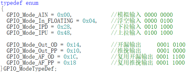
GPIO配置中,输入输出模式有八种分别是:模拟输入、浮空输入、下拉输入、上拉输入、开漏输出、推挽输出、复用开漏输出、复用推挽输出。
输出速度速度有三种:10mhz、2mhz、50mhz。
可以通过定义enum枚举类型来限定选项。
输入输出模式枚举类型:
输出速度枚举类型:

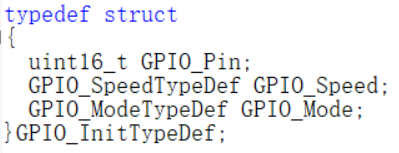
再定义一个初始化结构体类型,存放初始化GPIO引脚要用到的三个参数:引脚号、输出速度、输入输出模式。
对于初始化,官方库有个更详尽复杂的函数能替代这两个函数的功能(官方函数课上已讲解):
 ->
->

引入官方初始化函数并申明。
如何给初始化结构体赋值呢?
先定义新的GPIO_InitTypeDef初始化结构体类型,然后用“.”访问结构体中的元素。输入输出模式、速度用枚举变量里取的别名。
赋值完成以后将结构体的地址作为参数传入官方初始化函数。

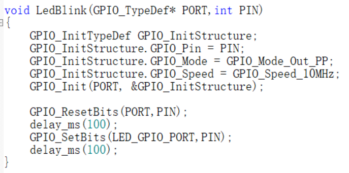
将灯闪烁功能整合成一个函数后:
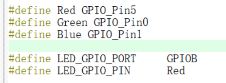
为了更好的程序可移植性多增加了一些宏定义:
整合以后的代码:
stm32f10x_gpio.c:
- #include "stm32f10x_gpio.h"
- void RCC_Enable(RCC_TypeDef *RCCx,uint16_t IOPortx)
- {
- RCCx->APB2ENR |=IOPortx;
- }
- void GPIO_SetBits(GPIO_TypeDef *GPIOx,uint16_t GPIO_Pin)
- {
- GPIOx->BSRR |= GPIO_Pin;
- }
- void GPIO_ResetBits(GPIO_TypeDef *GPIOx,uint16_t GPIO_Pin)
- {
- GPIOx->BRR |= GPIO_Pin;
- }
- void GPIO_Init(GPIO_TypeDef* GPIOx, GPIO_InitTypeDef* GPIO_InitStruct)
- {
- uint32_t currentmode = 0x00, currentpin = 0x00, pinpos = 0x00, pos = 0x00;
- uint32_t tmpreg = 0x00, pinmask = 0x00;
- /*---------------------- GPIO 模式配置 --------------------------*/
- // 把输入参数GPIO_Mode的低四位暂存在currentmode
- currentmode = ((uint32_t)GPIO_InitStruct->GPIO_Mode) & ((uint32_t)0x0F);
- // bit4是1表示输出,bit4是0则是输入
- // 判断bit4是1还是0,即首选判断是输入还是输出模式
- if ((((uint32_t)GPIO_InitStruct->GPIO_Mode) & ((uint32_t)0x10)) != 0x00)
- {
- // 输出模式则要设置输出速度
- currentmode |= (uint32_t)GPIO_InitStruct->GPIO_Speed;
- }
- /*-------------GPIO CRL 寄存器配置 CRL寄存器控制着低8位IO- -------*/
- // 配置端口低8位,即Pin0~Pin7
- if (((uint32_t)GPIO_InitStruct->GPIO_Pin & ((uint32_t)0x00FF)) != 0x00)
- {
- // 先备份CRL寄存器的值
- tmpreg = GPIOx->CRL;
- // 循环,从Pin0开始配对,找出具体的Pin
- for (pinpos = 0x00; pinpos < 0x08; pinpos++)
- {
- // pos的值为1左移pinpos位
- pos = ((uint32_t)0x01) << pinpos;
- // 令pos与输入参数GPIO_PIN作位与运算,为下面的判断作准备
- currentpin = (GPIO_InitStruct->GPIO_Pin) & pos;
- //若currentpin=pos,则找到使用的引脚
- if (currentpin == pos)
- {
- // pinpos的值左移两位(乘以4),因为寄存器中4个寄存器位配置一个引脚
- pos = pinpos << 2;
- //把控制这个引脚的4个寄存器位清零,其它寄存器位不变
- pinmask = ((uint32_t)0x0F) << pos;
- tmpreg &= ~pinmask;
- // 向寄存器写入将要配置的引脚的模式
- tmpreg |= (currentmode << pos);
- // 判断是否为下拉输入模式
- if (GPIO_InitStruct->GPIO_Mode == GPIO_Mode_IPD)
- {
- // 下拉输入模式,引脚默认置0,对BRR寄存器写1可对引脚置0
- GPIOx->BRR = (((uint32_t)0x01) << pinpos);
- }
- else
- {
- // 判断是否为上拉输入模式
- if (GPIO_InitStruct->GPIO_Mode == GPIO_Mode_IPU)
- {
- // 上拉输入模式,引脚默认值为1,对BSRR寄存器写1可对引脚置1
- GPIOx->BSRR = (((uint32_t)0x01) << pinpos);
- }
- }
- }
- }
- // 把前面处理后的暂存值写入到CRL寄存器之中
- GPIOx->CRL = tmpreg;
- }
- /*-------------GPIO CRH 寄存器配置 CRH寄存器控制着高8位IO- -----------*/
- // 配置端口高8位,即Pin8~Pin15
- if (GPIO_InitStruct->GPIO_Pin > 0x00FF)
- {
- // // 先备份CRH寄存器的值
- tmpreg = GPIOx->CRH;
- // 循环,从Pin8开始配对,找出具体的Pin
- for (pinpos = 0x00; pinpos < 0x08; pinpos++)
- {
- pos = (((uint32_t)0x01) << (pinpos + 0x08));
- // pos与输入参数GPIO_PIN作位与运算
- currentpin = ((GPIO_InitStruct->GPIO_Pin) & pos);
- //若currentpin=pos,则找到使用的引脚
- if (currentpin == pos)
- {
- //pinpos的值左移两位(乘以4),因为寄存器中4个寄存器位配置一个引脚
- pos = pinpos << 2;
- //把控制这个引脚的4个寄存器位清零,其它寄存器位不变
- pinmask = ((uint32_t)0x0F) << pos;
- tmpreg &= ~pinmask;
- // 向寄存器写入将要配置的引脚的模式
- tmpreg |= (currentmode << pos);
- // 判断是否为下拉输入模式
- if (GPIO_InitStruct->GPIO_Mode == GPIO_Mode_IPD)
- {
- // 下拉输入模式,引脚默认置0,对BRR寄存器写1可对引脚置0
- GPIOx->BRR = (((uint32_t)0x01) << (pinpos + 0x08));
- }
- // 判断是否为上拉输入模式
- if (GPIO_InitStruct->GPIO_Mode == GPIO_Mode_IPU)
- {
- // 上拉输入模式,引脚默认值为1,对BSRR寄存器写1可对引脚置1
- GPIOx->BSRR = (((uint32_t)0x01) << (pinpos + 0x08));
- }
- }
- }
- // 把前面处理后的暂存值写入到CRH寄存器之中
- GPIOx->CRH = tmpreg;
- }
- }
stm32f10x_gpio.h:
- #ifndef __STM32F10X_GPIO_H
- #define __STM32F10X_GPIO_H
- #include "stm32f10x.h"
- #define IOPortA ((uint16_t)0x0004) //GPIOA
- #define IOPortB ((uint16_t)0x0008) //GPIOB
- #define IOPortC ((uint16_t)0x0010) //GPIOC
- #define IOPortD ((uint16_t)0x0020) //GPIOD
- #define IOPortE ((uint16_t)0x0040) //GPIOE
- #define IOPortF ((uint16_t)0x0080) //GPIOF
- #define IOPortG ((uint16_t)0x0100) //GPIOG
- #define GPIO_Pin0 ((uint16_t)0x0001) //选择Pin0
- #define GPIO_Pin1 ((uint16_t)0x0002) //选择Pin1
- #define GPIO_Pin2 ((uint16_t)0x0004) //选择Pin2
- #define GPIO_Pin3 ((uint16_t)0x0008) //选择Pin3
- #define GPIO_Pin4 ((uint16_t)0x0010) //选择Pin4
- #define GPIO_Pin5 ((uint16_t)0x0020) //选择Pin5
- #define GPIO_Pin6 ((uint16_t)0x0040) //选择Pin6
- #define GPIO_Pin7 ((uint16_t)0x0080) //选择Pin7
- #define GPIO_Pin8 ((uint16_t)0x0100) //选择Pin8
- #define GPIO_Pin9 ((uint16_t)0x0200) //选择Pin9
- #define GPIO_Pin10 ((uint16_t)0x0400) //选择Pin10
- #define GPIO_Pin11 ((uint16_t)0x0800) //选择Pin11
- #define GPIO_Pin12 ((uint16_t)0x1000) //选择Pin12
- #define GPIO_Pin13 ((uint16_t)0x2000) //选择Pin13
- #define GPIO_Pin14 ((uint16_t)0x4000) //选择Pin14
- #define GPIO_Pin15 ((uint16_t)0x8000) //选择Pin15
- #define GPIO_PinAll ((uint16_t)0xFFFF) //选择全部Pin
- typedef enum
- {
- GPIO_Speed_10MHz = 1,//10mhz 01
- GPIO_Speed_2MHz, //2mhz 10
- GPIO_Speed_50MHz //50mhz 11
- } GPIO_SpeedTypeDef;
- typedef enum
- {
- GPIO_Mode_AIN = 0x00, //模拟输入 0000 0000
- GPIO_Mode_In_FLOATING = 0x04, //浮空输入 0000 0100
- GPIO_Mode_IPD = 0x28, //下拉输入 0010 1000
- GPIO_Mode_IPU = 0x48, //上拉输入 0100 1000
- GPIO_Mode_Out_OD = 0x14, //开漏输出 0001 0100
- GPIO_Mode_Out_PP = 0x10, //推挽输出 0001 0000
- GPIO_Mode_AF_OD = 0x1C, //复用开漏输出 0001 1100
- GPIO_Mode_AF_PP = 0x18 //复用推挽输出 0001 1000
- } GPIO_ModeTypeDef;
- typedef struct
- {
- uint16_t GPIO_Pin;
- GPIO_SpeedTypeDef GPIO_Speed;
- GPIO_ModeTypeDef GPIO_Mode;
- } GPIO_InitTypeDef;
- void RCC_Enable(RCC_TypeDef *RCCx,uint16_t IOPortx);
- void GPIO_SetBits(GPIO_TypeDef *GPIOx,uint16_t GPIO_Pin);
- void GPIO_ResetBits(GPIO_TypeDef *GPIOx,uint16_t GPIO_Pin);
- void GPIO_Init(GPIO_TypeDef* GPIOx, GPIO_InitTypeDef* GPIO_InitStruct);
- #endif /*__STM32F10X_GPIO_H*/
stm32f10x.h:
- #ifndef __STM32F10X_H
- #define __STM32F10X_H
- //用来存放STM32寄存器映射的代码
- //外设 peripheral
- #define PERIPH_BASE ((unsigned int)0x40000000)
- #define APB2PERIPH_BASE (PERIPH_BASE + 0x10000)
- #define AHBPERIPH_BASE (PERIPH_BASE + 0x20000)
- #define RCC_BASE (AHBPERIPH_BASE+0x1000)
- #define GPIOB_BASE (APB2PERIPH_BASE+0x0C00)
- #define RCC_APB2ENR *(unsigned int*)(RCC_BASE + 0x18)
- #define GPIOB_CRL *(unsigned int*)(GPIOB_BASE + 0x00)
- #define GPIOB_CRH *(unsigned int*)(GPIOB_BASE + 0x04)
- #define GPIOB_IDR *(unsigned int*)(GPIOB_BASE + 0x08)
- #define GPIOB_ODR *(unsigned int*)(GPIOB_BASE + 0x0C)
- #define GPIOB_BSRR *(unsigned int*)(GPIOB_BASE + 0x10)
- #define GPIOB_BRR *(unsigned int*)(GPIOB_BASE + 0x14)
- #define GPIOB_LCKR *(unsigned int*)(GPIOB_BASE + 0x18)
- typedef unsigned int uint32_t;
- typedef unsigned short uint16_t;
- typedef struct
- {
- uint32_t CR;
- uint32_t CFGR;
- uint32_t CIR;
- uint32_t APB2RSTR;
- uint32_t APB1RSTR;
- uint32_t AHBENR;
- uint32_t APB2ENR;
- uint32_t APB1ENR;
- uint32_t BDCR;
- uint32_t CSR;
- } RCC_TypeDef;
- #define RCC ((RCC_TypeDef*)RCC_BASE)
- typedef struct
- {
- uint32_t CRL;
- uint32_t CRH;
- uint32_t IDR;
- uint32_t ODR;
- uint32_t BSRR;
- uint32_t BRR;
- uint32_t LCKR;
- } GPIO_TypeDef;
- #define GPIOB ((GPIO_TypeDef*)GPIOB_BASE)
- #endif /*__STM32F10X_H*/
红灯闪烁:
main.c:
- #include "stm32f10x.h"
- #include "stm32f10x_gpio.h"
- #define Red GPIO_Pin5
- #define Green GPIO_Pin0
- #define Blue GPIO_Pin1
- #define LED_GPIO_PORT GPIOB
- void delay_us(int delay_us);
- void delay_ms(int delay_ms);
- void LedBlink(GPIO_TypeDef* PORT,int PIN);
- int main(void)
- {
- RCC_Enable(RCC,IOPortB);
- while(1)
- {
- LedBlink(LED_GPIO_PORT,Red);
- }
- }
- //函数体为空,目的是为了骗过编译器不报错
- void SystemInit(void)
- {}
- //微秒级的延时
- void delay_us(int delay_us)
- {
- volatile unsigned int num;
- volatile unsigned int t;
- for (num = 0; num < delay_us; num++)
- {
- t = 11;
- while (t != 0)
- {
- t--;
- }
- }
- }
- //毫秒级的延时
- void delay_ms(int delay_ms)
- {
- volatile unsigned int num;
- for (num = 0; num < delay_ms; num++)
- {
- delay_us(1000);
- }
- }
- void LedBlink(GPIO_TypeDef* PORT,int PIN)
- {
- GPIO_InitTypeDef GPIO_InitStructure;
- GPIO_InitStructure.GPIO_Pin = PIN;
- GPIO_InitStructure.GPIO_Mode = GPIO_Mode_Out_PP;
- GPIO_InitStructure.GPIO_Speed = GPIO_Speed_10MHz;
- GPIO_Init(PORT, &GPIO_InitStructure);
- GPIO_ResetBits(PORT,PIN);
- delay_ms(100);
- GPIO_SetBits(LED_GPIO_PORT,PIN);
- delay_ms(100);
- }
红蓝交替:
main.c:
- #include "stm32f10x.h"
- #include "stm32f10x_gpio.h"
- #define Red GPIO_Pin5
- #define Green GPIO_Pin0
- #define Blue GPIO_Pin1
- #define LED_GPIO_PORT GPIOB
- void delay_us(int delay_us);
- void delay_ms(int delay_ms);
- void LedBlink(GPIO_TypeDef* PORT,int PIN);
- int main(void)
- {
- RCC_Enable(RCC,IOPortB);
- while(1)
- {
- LedBlink(LED_GPIO_PORT,Red);
- LedBlink(LED_GPIO_PORT,Blue);
- }
- }
- //函数体为空,目的是为了骗过编译器不报错
- void SystemInit(void)
- {}
- //微秒级的延时
- void delay_us(int delay_us)
- {
- volatile unsigned int num;
- volatile unsigned int t;
- for (num = 0; num < delay_us; num++)
- {
- t = 11;
- while (t != 0)
- {
- t--;
- }
- }
- }
- //毫秒级的延时
- void delay_ms(int delay_ms)
- {
- volatile unsigned int num;
- for (num = 0; num < delay_ms; num++)
- {
- delay_us(1000);
- }
- }
- void LedBlink(GPIO_TypeDef* PORT,int PIN)
- {
- GPIO_InitTypeDef GPIO_InitStructure;
- GPIO_InitStructure.GPIO_Pin = PIN;
- GPIO_InitStructure.GPIO_Mode = GPIO_Mode_Out_PP;
- GPIO_InitStructure.GPIO_Speed = GPIO_Speed_10MHz;
- GPIO_Init(PORT, &GPIO_InitStructure);
- GPIO_ResetBits(PORT,PIN);
- delay_ms(100);
- GPIO_SetBits(LED_GPIO_PORT,PIN);
- //delay_ms(100);
- }
|