博士
最后登录1970-1-1
在线时间 小时
注册时间2022-7-18
|
拿到启明6M5开发板,第一感觉比较精简,没有想象中那么大,但外部资源依旧很丰富,今天来开箱点个灯试试。
一、硬件实物

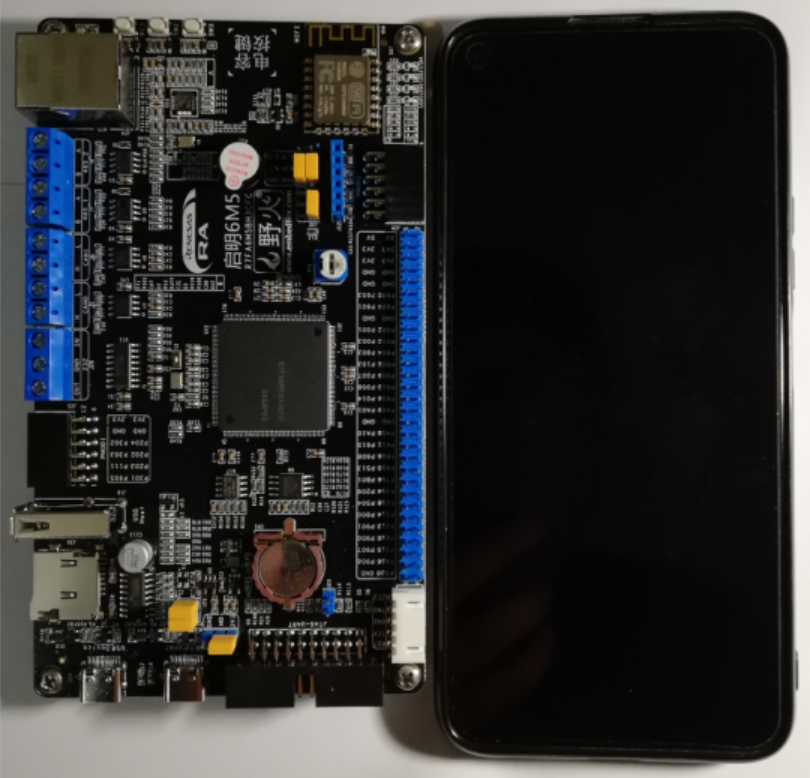
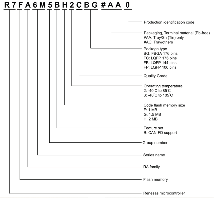
如上图所示,长宽与6.5英寸手机相比略有偏差。这块板子有两个Type-C接口可做为供电接口,MCU为瑞萨的R7FA6M5BH3CFC。关于瑞萨产品的命名规则如下:
二、获取必备软件包
开发之前,我们需要准备必要的开发工具,这里我们可以前往瑞萨的官网获取到。
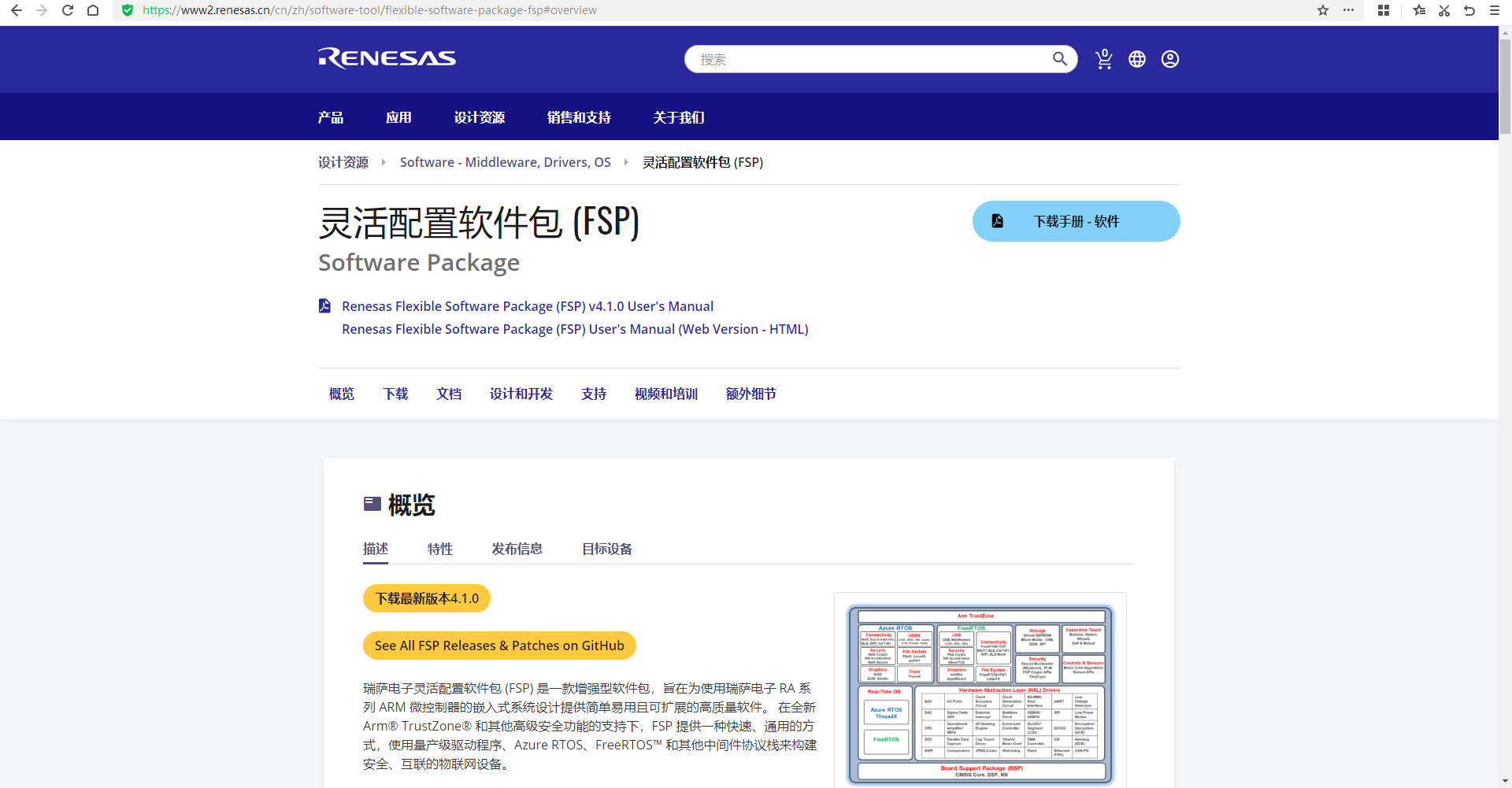
获取灵活配置软件包(FSP)的最新版V4_1_0,当然需要注册好瑞萨网站个人账户才能顺利下载。
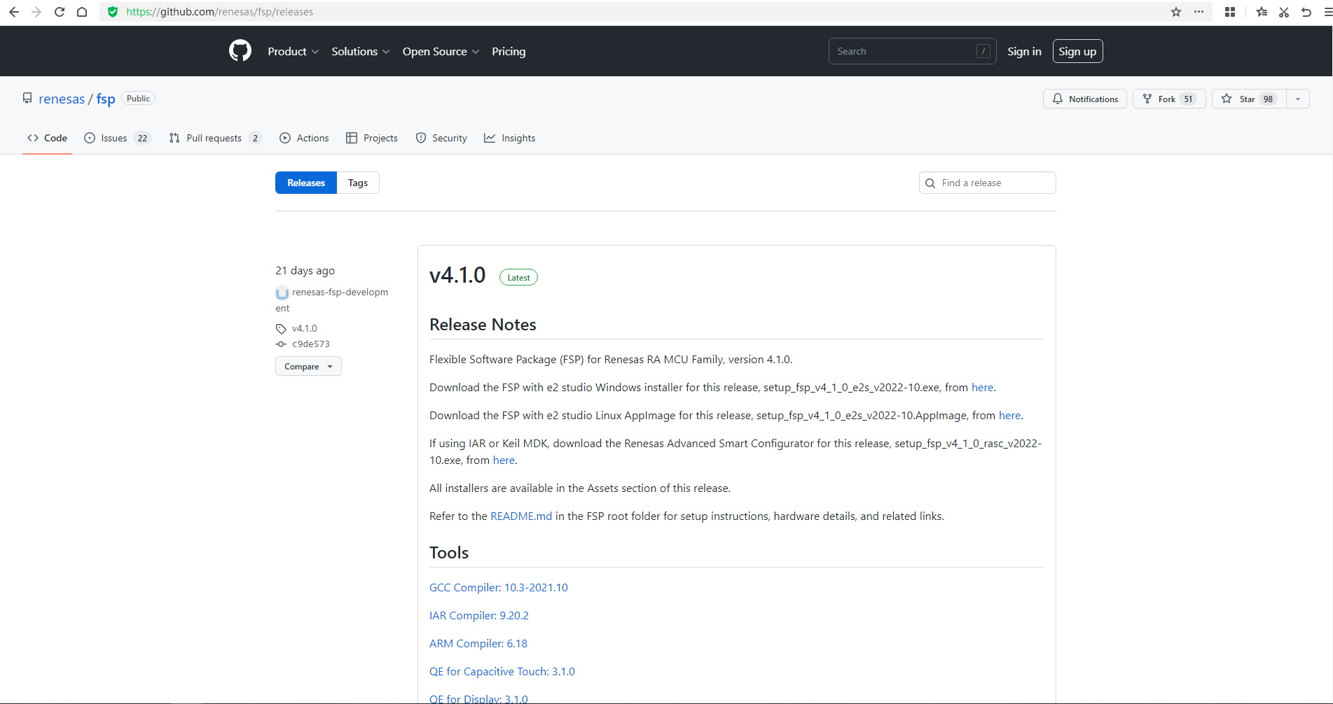
获取瑞萨官方提供的最新“setup_fsp_v4_1_0_e2s_v2022-10.exe”与“Renesas.RA_DFP.4.1.0.pack”可以通过访问https://github.com/renesas/fsp/releases获取到的。
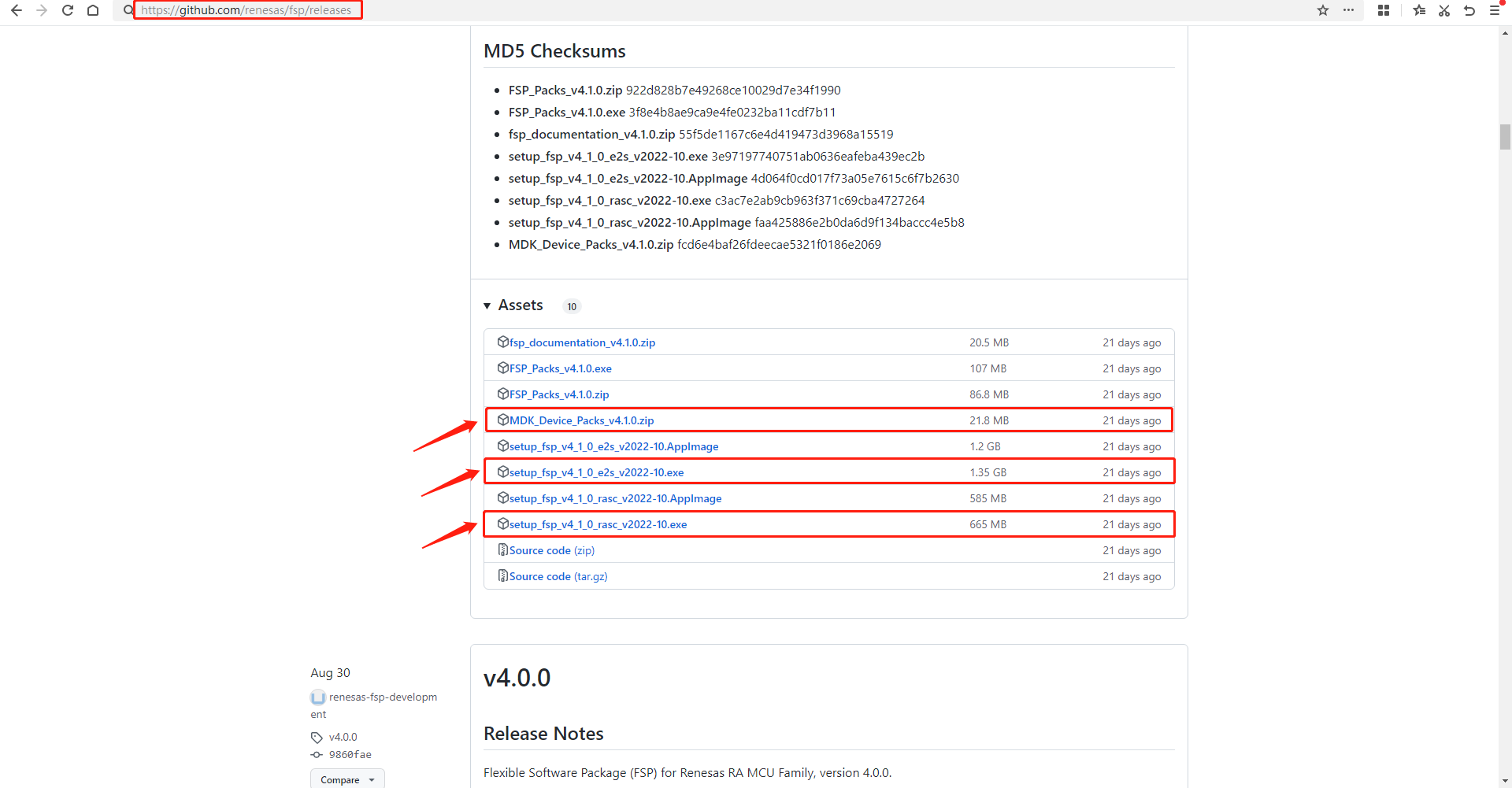
如果我们不习惯使用官方提供的“e2 studio”,灵活配置工具FSP支持导出IAR、Keil工程,官方也提供了参考培训视频,使用方便快捷。

三、搭建开发环境
安装下载后的必备软件工具,这里需注意的是,在安装“e2 studio”或“rasc”时,win10系统需要有"Microsoft Visual C++ 2015-2022"环境,如果没有则会安装失败,这里提供一下安装"Microsoft Visual C++ 2015-2022"的64位安装包。
 VC_redist.x64.zip
(24.05 MB, 下载次数: 3)
傻瓜式安装完“e2 studio”与“rasc”后,还需要安装keil支持包“Renesas.RA_DFP.4.1.0.pack”。
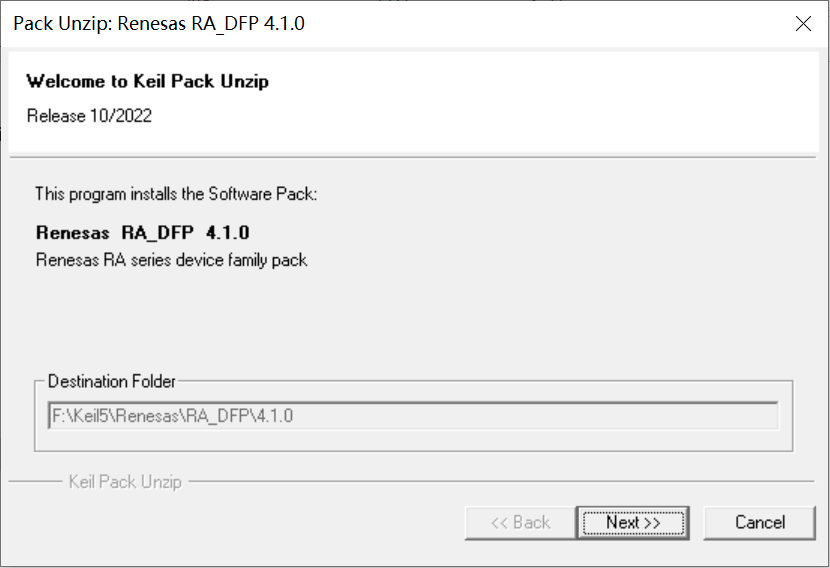
四、构建工程
这里我们使用“rasc”工具,也就是“FSP Smart Configurator”来快速配置基于MDK的工程。双击打开“\fsp_v4_1_0_rasc\eclipse”目录下的“rasc.exe”,选择好对应的芯片型号,并勾选将要导出工程适用的IDE类型。
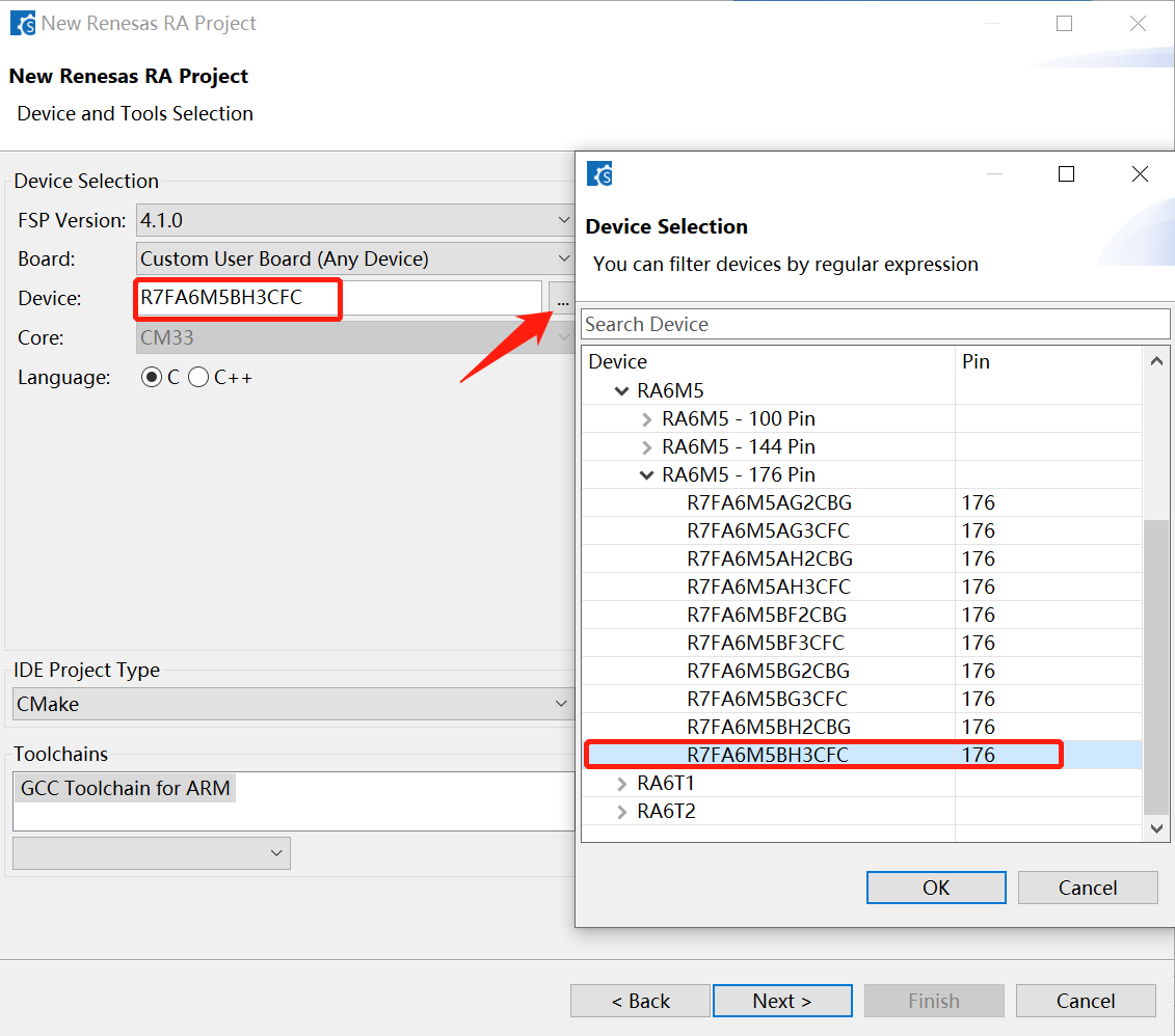
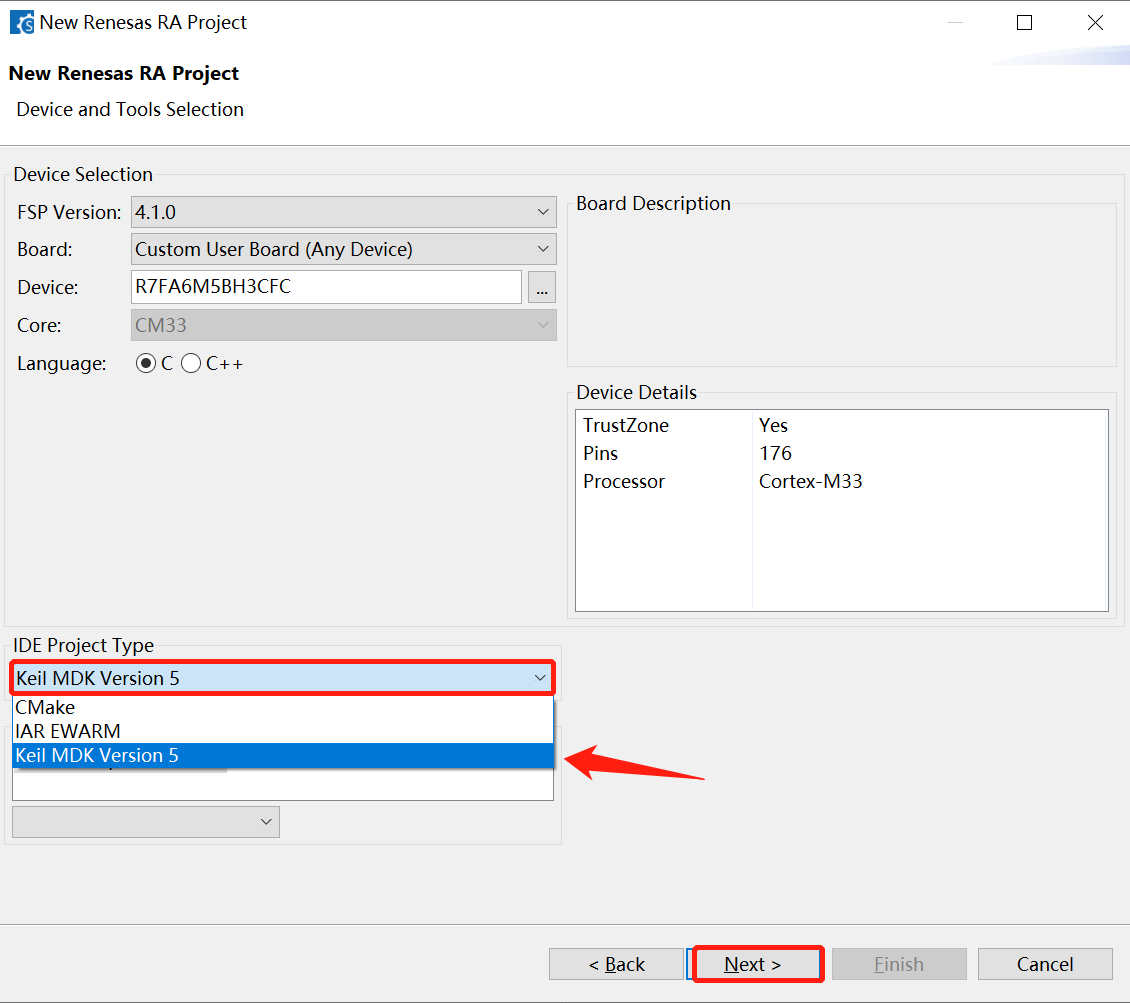
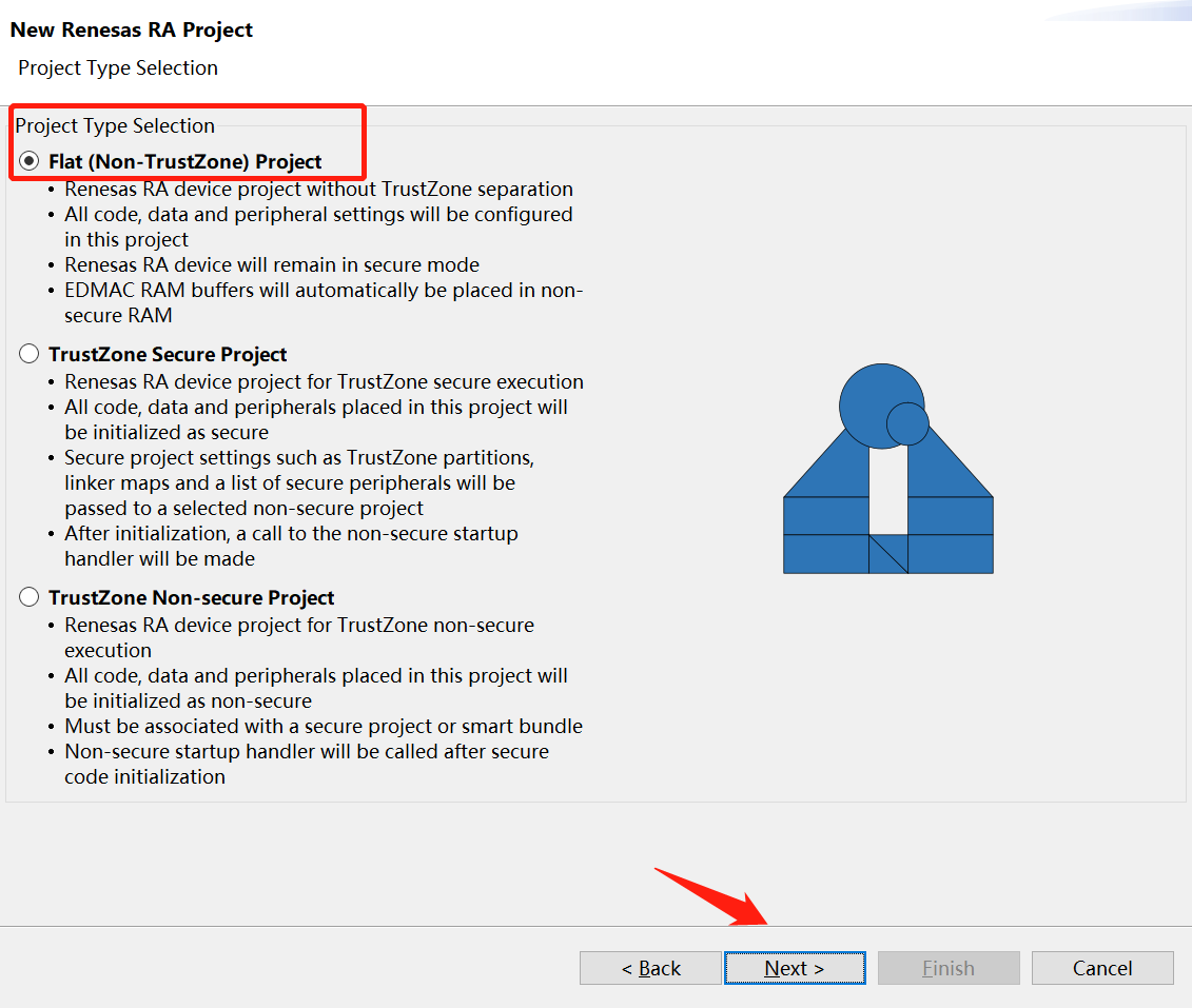
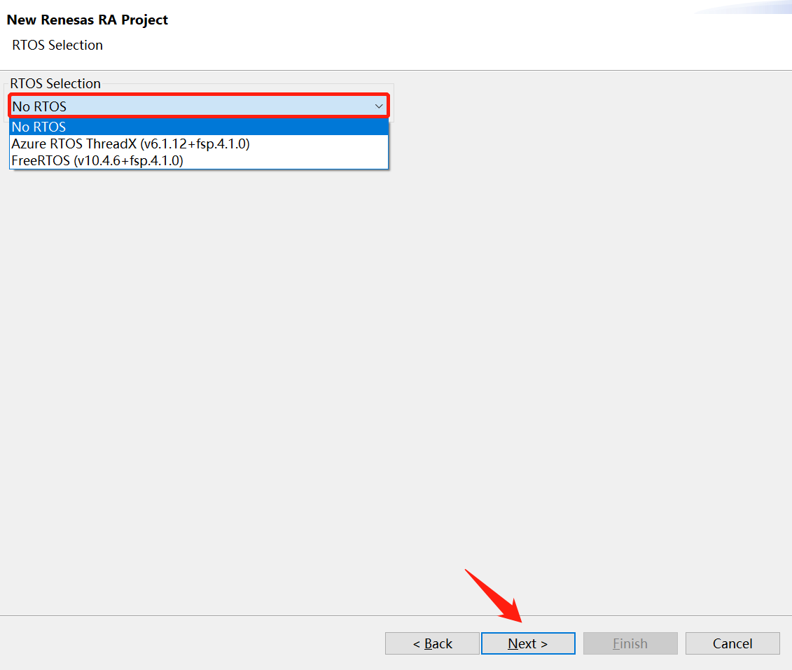
接着一路默认选择即可,即所配置的工程“No-TrustZone”,不跑实时系统。
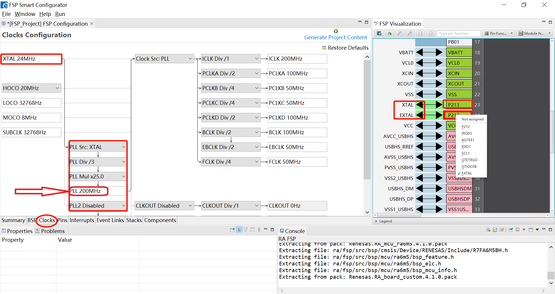
接着找到“Clocks”标签栏,将P212、P213管脚设置成外部时钟接口,其默认分频参数即可,即PLL 200MHz。
由野火官方提供的SDK中,基于启明RA6M5板子的原理图“ebf410069_sch”有关于LED的管脚分布介绍。
 ebf410069_sch.pdf
(288.04 KB, 下载次数: 1)
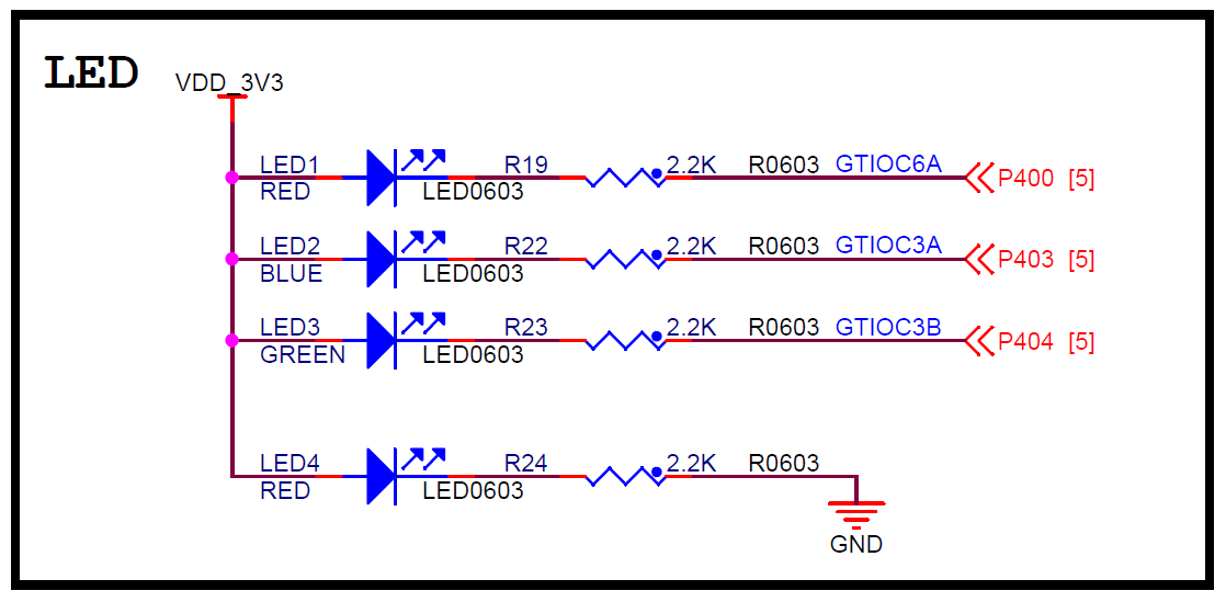
由上图可知,点亮LED1、LED2、LED3需要将P400、P403、P404输出低,因此选中对应管脚,配置成P400、P403、P404,并设置默认为输出高电平。
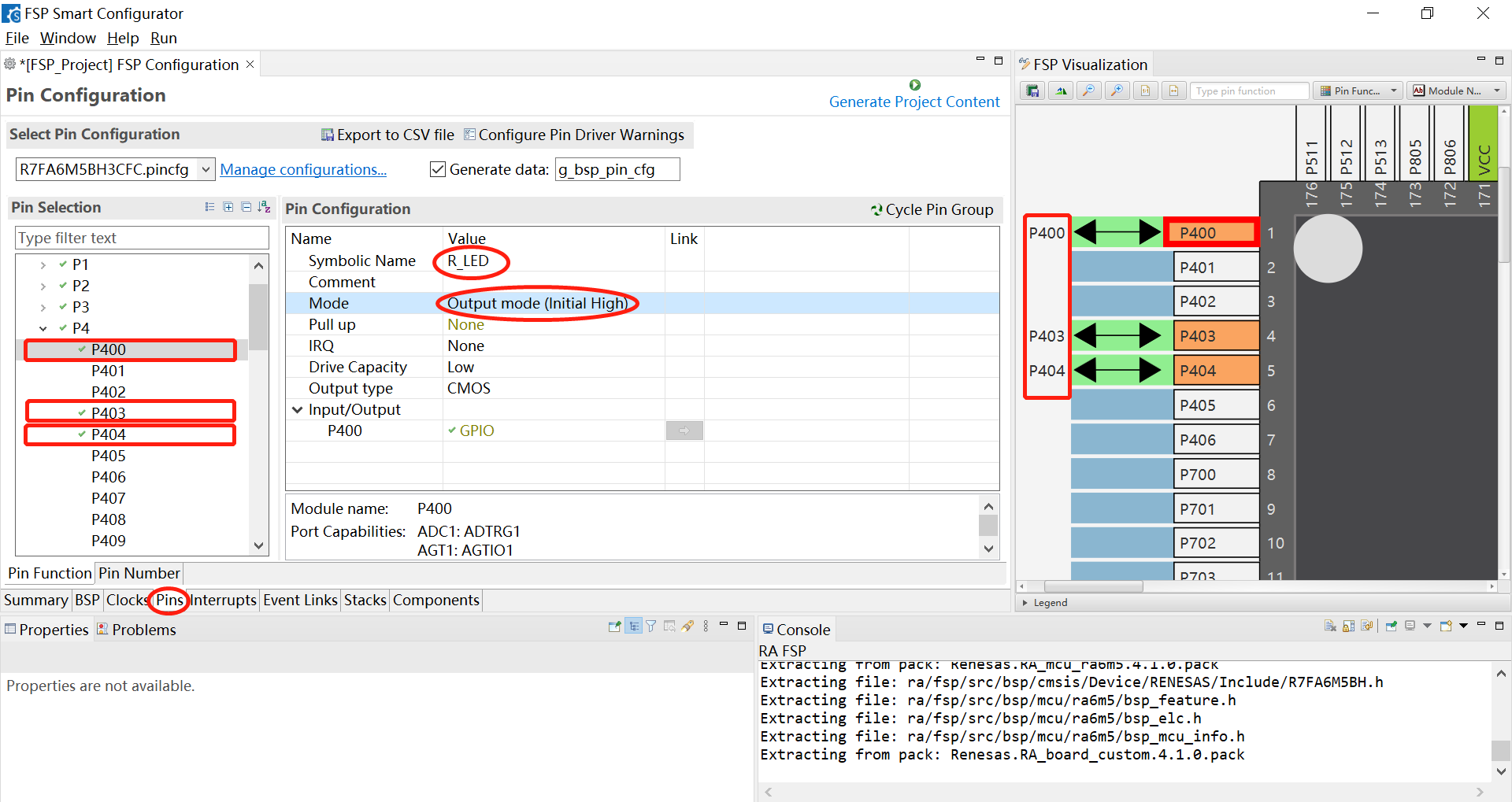
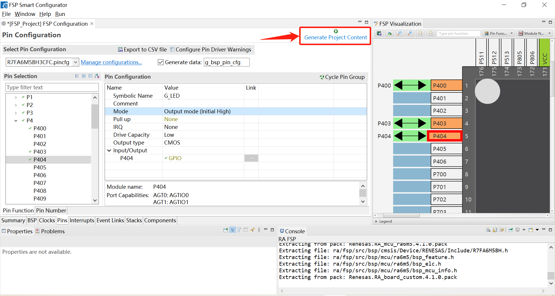
点击工具上“Generate Project Content”图标,即在“rasc”软件启动初始时设置的保存路径下生成了Keil工程。
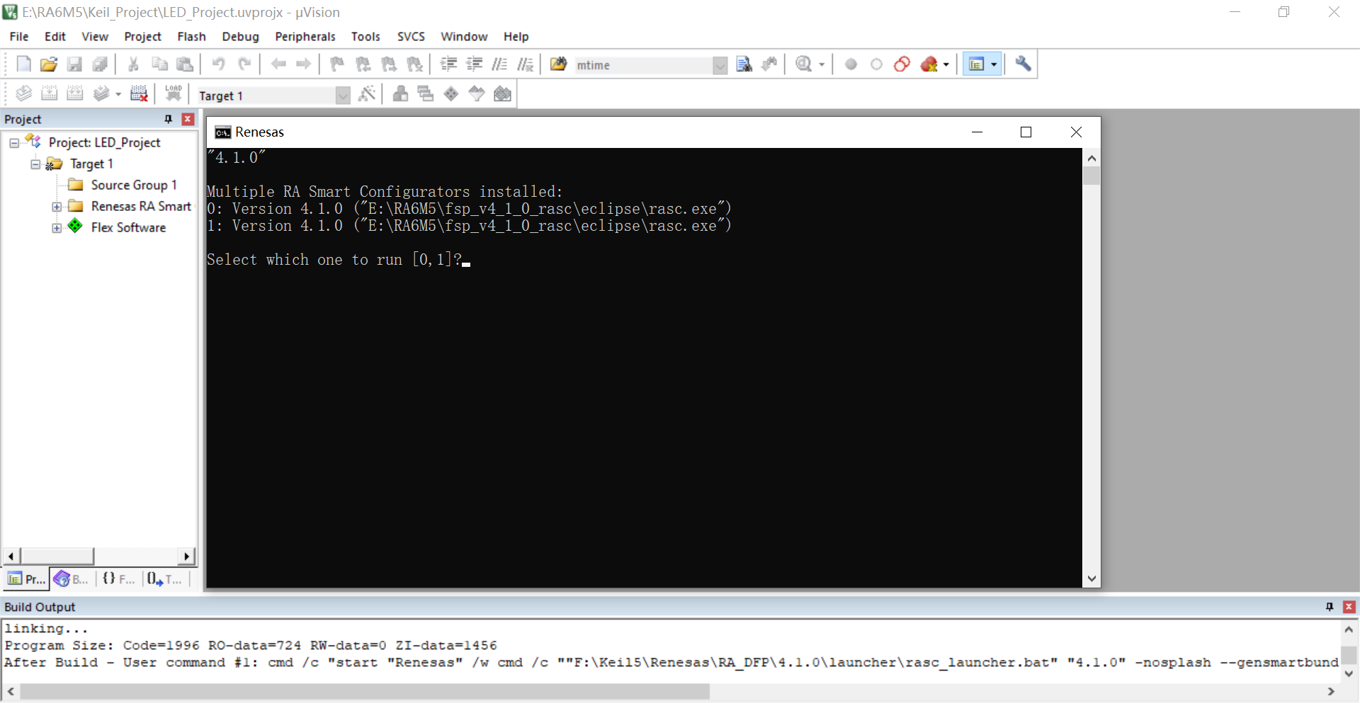
接着使用Keil5打开工程,直接进行全编译,结果弹出如下界面,输入“0”,回车即可。
我们需要定义端口和引脚号的枚举类型, 用来表示某个要操控的某个管脚,这里将端口和管脚号分开出来单独定义。
在r_ioport.c源文件中添加部分代码
- /* 读引脚电平*/
- uint32_t IOPORT_PinRead(IO_Port_t port, IO_Pin_t pin)
- {
- /*Read pin level.*/
- return R_PFS->PORT[port >> 8].PIN[pin].PmnPFS_b.PIDR;
- }
- /* 写引脚电平*/
- void IOPORT_PinWrite(IO_Port_t port, IO_Pin_t pin, IO_Level_t level)
- {
- uint32_t pfs_bits = R_PFS->PORT[port >> 8].PIN[pin].PmnPFS; //读寄存器PmnPFS
- pfs_bits &= ~(uint32_t)0x1; //清零PODR 位
- R_PFS->PORT[port >> 8].PIN[pin].PmnPFS = (pfs_bits | level);
- }
- /* 翻转引脚电平*/
- void IOPORT_PinToggle(IO_Port_t port, IO_Pin_t pin)
- {
- uint32_t pfs_bits = R_PFS->PORT[port >> 8].PIN[pin].PmnPFS; //读寄存器PmnPFS
- pfs_bits ^= (uint32_t)0x1; //取反PODR 位
- R_PFS->PORT[port >> 8].PIN[pin].PmnPFS = pfs_bits;
- }
- /* 引脚访问使能*/
- void IOPORT_PinAccessEnable(void)
- {
- R_PMISC->PWPR = 0; ///< Clear BOWI bit - writing to PFSWE bit enabled
- R_PMISC->PWPR = 1U << 6U; ///< Set PFSWE bit - writing to PFS register enabled
- }
- /* 引脚访问禁止*/
- void IOPORT_PinAccessDisable(void)
- {
- R_PMISC->PWPR = 0; ///< Clear PFSWE bit - writing to PFS register disabled
- R_PMISC->PWPR = 1U << 7U; ///< Set BOWI bit - writing to PFSWE bit disabled
- }
- /* IOPORT 初始化函数*/
- void IOPORT_Init(IOPORT_Init_t *ioport_init)
- {
- uint32_t pfs_bits = 0; //不读取寄存器PmnPFS
- if(ioport_init->Mode == IO_MODE_GPIO) //如果引脚用作普通GPIO 功能
- {
- if(ioport_init->Dir == IO_DIR_INPUT) /* 用作输入模式*/
- {
- pfs_bits |= (ioport_init->Pull) << 4; //设置输入上拉
- }
- else if(ioport_init->Dir == IO_DIR_OUTPUT) /* 用作输出模式*/
- {
- pfs_bits |= (ioport_init->Dir) << 2; //设置为输出
- pfs_bits |= (ioport_init->Level) << 0; //设置输出电平
- pfs_bits |= (ioport_init->Mode) << 6; //设置输出模式
- pfs_bits |= (ioport_init->Drive) << 10; //设置输出驱动能力
- }
- }
- else
- {
- }
- /* 写入配置到寄存器PmnPFS */
- R_PFS->PORT[ioport_init->Port >> 8].PIN[ioport_init->Pin].PmnPFS = pfs_bits;
- }
- /* IOPORT 端口定义*/
- typedef enum io_port
- {
- IO_PORT_00 = 0x0000, ///< IO port 0
- IO_PORT_01 = 0x0100, ///< IO port 1
- IO_PORT_02 = 0x0200, ///< IO port 2
- IO_PORT_03 = 0x0300, ///< IO port 3
- IO_PORT_04 = 0x0400, ///< IO port 4
- IO_PORT_05 = 0x0500, ///< IO port 5
- IO_PORT_06 = 0x0600, ///< IO port 6
- IO_PORT_07 = 0x0700, ///< IO port 7
- IO_PORT_08 = 0x0800, ///< IO port 8
- IO_PORT_09 = 0x0900, ///< IO port 9
- IO_PORT_10 = 0x0A00, ///< IO port 10
- IO_PORT_11 = 0x0B00, ///< IO port 11
- IO_PORT_12 = 0x0C00, ///< IO port 12
- IO_PORT_13 = 0x0D00, ///< IO port 13
- IO_PORT_14 = 0x0E00, ///< IO port 14
- } IO_Port_t;
- /* IOPORT 引脚定义*/
- typedef enum io_pin
- {
- IO_PIN_00 = 0x0000, ///< IO port 0 pin 0
- IO_PIN_01 = 0x0001, ///< IO port 0 pin 1
- IO_PIN_02 = 0x0002, ///< IO port 0 pin 2
- IO_PIN_03 = 0x0003, ///< IO port 0 pin 3
- IO_PIN_04 = 0x0004, ///< IO port 0 pin 4
- IO_PIN_05 = 0x0005, ///< IO port 0 pin 5
- IO_PIN_06 = 0x0006, ///< IO port 0 pin 6
- IO_PIN_07 = 0x0007, ///< IO port 0 pin 7
- IO_PIN_08 = 0x0008, ///< IO port 0 pin 8
- IO_PIN_09 = 0x0009, ///< IO port 0 pin 9
- IO_PIN_10 = 0x000A, ///< IO port 0 pin 10
- IO_PIN_11 = 0x000B, ///< IO port 0 pin 11
- IO_PIN_12 = 0x000C, ///< IO port 0 pin 12
- IO_PIN_13 = 0x000D, ///< IO port 0 pin 13
- IO_PIN_14 = 0x000E, ///< IO port 0 pin 14
- IO_PIN_15 = 0x000F, ///< IO port 0 pin 15
- } IO_Pin_t;
- /*IO引脚模式*/
- typedef enum
- {
- IO_MODE_GPIO = 0, /* 普通GPIO 功能*/
- IO_MODE_AF = 1, /* 复用功能*/
- IO_MODE_AN = 2 /* 模拟输入输出功能*/
- } IO_Mode_t;
- /*IO引脚方向*/
- typedef enum
- {
- IO_DIR_INPUT = 0, //引脚用作输入功能
- IO_DIR_OUTPUT = 1 //引脚用作输出功能
- } IO_Dir_t;
- /*IO引脚输出类型*/
- typedef enum
- {
- IO_OTYPE_PP = 0x00, /*!< 推挽模式*/
- IO_OTYPE_OD = 0x01 /*!< 开漏模式*/
- } IO_OType_t;
- /*IO引脚输出能力*/
- typedef enum
- {
- IO_DRIVE_LOW = 0, //Low drive
- IO_DRIVE_MIDDLE = 1, //Middle drive
- IO_DRIVE_HSHD = 2, //High-speed high-drive
- IO_DRIVE_HIGH = 3 //High drive
- } IO_DriveCapability_t;
- /*IO引脚输出电平*/
- typedef enum io_level
- {
- IO_LEVEL_LOW = 0, //< Low
- IO_LEVEL_HIGH //< High
- } IO_Level_t;
- /*IO引脚输入上下拉*/
- typedef enum
- {
- IO_NO_PULL = 0x00u, /* 浮空*/
- IO_PULL_UP = 0x01u, /* 上拉*/
- //IO_PULL_DOWN = 0x02u /* RA6M5 引脚没有下拉功能*/
- } IO_Pull_t;
- /*IOPORT初始化结构体类型定义*/
- typedef struct
- {
- IO_Port_t Port;
- IO_Pin_t Pin;
- IO_Mode_t Mode;
- IO_Dir_t Dir;
- IO_OType_t OType;
- IO_DriveCapability_t Drive;
- IO_Level_t Level;
- IO_Pull_t Pull;
- }IOPORT_Init_t;
- /*IO操作函数(调用一次只能操作一个IO 引脚)*/
- uint32_t IOPORT_PinRead (IO_Port_t port, IO_Pin_t pin);
- void IOPORT_PinWrite (IO_Port_t port, IO_Pin_t pin, IO_Level_t level);
- void IOPORT_PinToggle (IO_Port_t port, IO_Pin_t pin);
- void IOPORT_PinAccessEnable (void);
- void IOPORT_PinAccessDisable (void);
- /*IO初始化函数(调用一次只能初始化一个IO 引脚)*/
- void IOPORT_Init (IOPORT_Init_t *ioport_init);
- void hal_entry(void)
- {
- /* TODO: add your own code here */
- /* 调用取消写保护函数*/
- IOPORT_PinAccessEnable();
- /* 使用IOPORT 初始化结构体和调用初始化函数来配置PFS 寄存器*/
- IOPORT_Init_t led_io_init;
- led_io_init.Port = IO_PORT_04;
- led_io_init.Pin = IO_PIN_00;
- led_io_init.Mode = IO_MODE_GPIO; //普通GPIO 模式,而不是复用功能模式或其他的
- led_io_init.Dir = IO_DIR_OUTPUT;
- led_io_init.OType = IO_OTYPE_PP;
- led_io_init.Drive = IO_DRIVE_LOW;
- led_io_init.Level = IO_LEVEL_HIGH; //输出高电平(LED 熄灭)
- IOPORT_Init(&led_io_init); //调用初始化函数,进行LED1 引脚初始化
- led_io_init.Pin = IO_PIN_03; //更换引脚号
- IOPORT_Init(&led_io_init); //结构体其他属性不变,再次调用初始化函数,进行LED引脚初始化
- led_io_init.Pin = IO_PIN_04; //更换引脚号
- IOPORT_Init(&led_io_init); //结构体其他属性不变,再次调用初始化函数,进行LED3引脚初始化
- /** 此时3 个LED 灯的引脚默认输出的是高电平,所以3 个LED 灯都会默认不亮
- * 我们先打开所有LED 灯,然后在while 循环里让LED1 闪烁:每秒钟翻转一次状态
- */
- IOPORT_PinWrite(IO_PORT_04, IO_PIN_00, IO_LEVEL_LOW); //点亮LED1
- IOPORT_PinWrite(IO_PORT_04, IO_PIN_03, IO_LEVEL_LOW); //点亮LED2
- IOPORT_PinWrite(IO_PORT_04, IO_PIN_04, IO_LEVEL_LOW); //点亮LED3
- while(1)
- {
- /*使用函数IOPORT_PinToggle 翻转LED1引脚电平*/
- IOPORT_PinToggle(IO_PORT_04, IO_PIN_00);
- R_BSP_SoftwareDelay(50, BSP_DELAY_UNITS_MILLISECONDS);
- IOPORT_PinToggle(IO_PORT_04, IO_PIN_03);
- R_BSP_SoftwareDelay(50, BSP_DELAY_UNITS_MILLISECONDS);
- IOPORT_PinToggle(IO_PORT_04, IO_PIN_04);
- R_BSP_SoftwareDelay(50, BSP_DELAY_UNITS_MILLISECONDS);
- IOPORT_PinWrite(IO_PORT_04, IO_PIN_00, IO_LEVEL_HIGH);
- IOPORT_PinWrite(IO_PORT_04, IO_PIN_03, IO_LEVEL_HIGH);
- IOPORT_PinWrite(IO_PORT_04, IO_PIN_04, IO_LEVEL_HIGH);
- R_BSP_SoftwareDelay(500, BSP_DELAY_UNITS_MILLISECONDS);
- }
- #if BSP_TZ_SECURE_BUILD
- /* Enter non-secure code */
- R_BSP_NonSecureEnter();
- #endif
- }
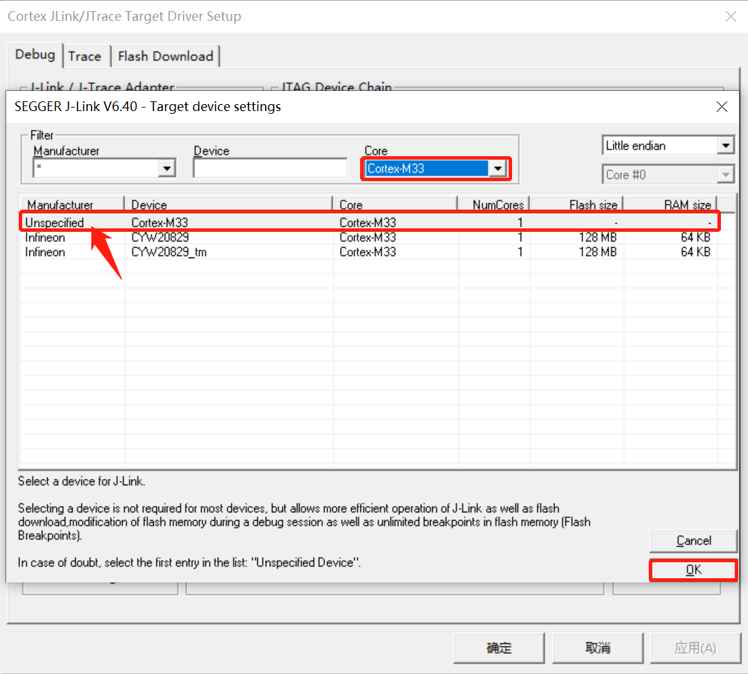
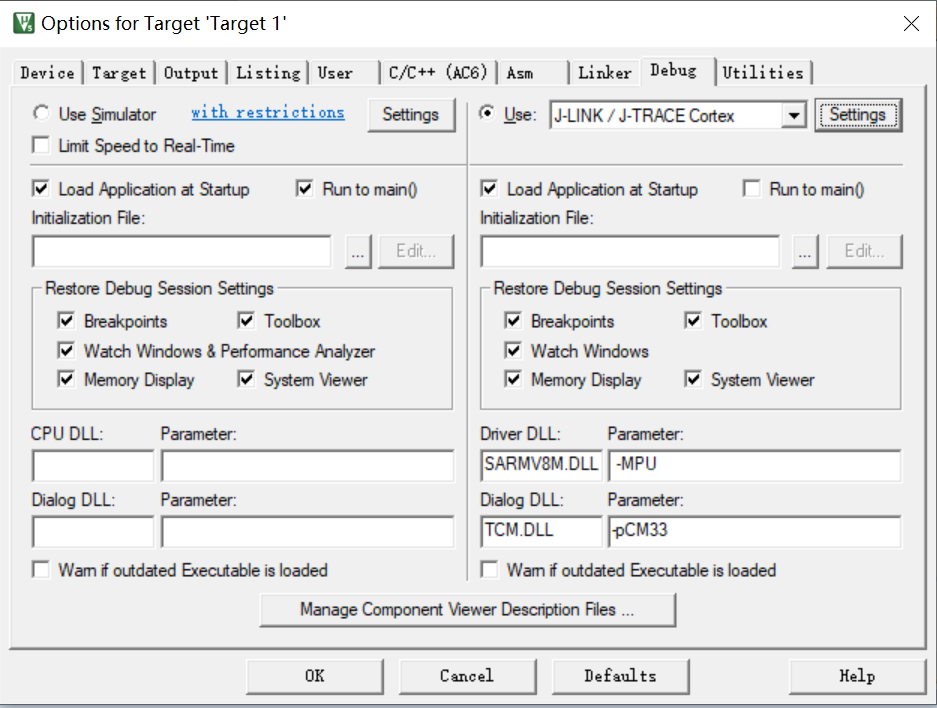
编译完成后,使用Type-C接口的数据线给板卡上电,连接好JLink调试器。在Keil魔法棒下找JLink调试器,首次使用会弹出如下对话框。
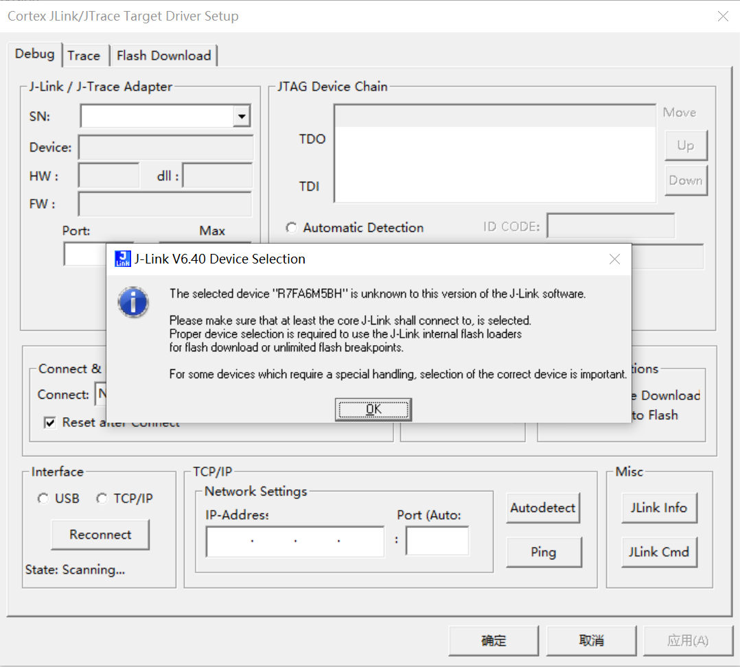
这里点击“确定”后,在接下来的对话框中,我们搜索M33,选择第一项即可。
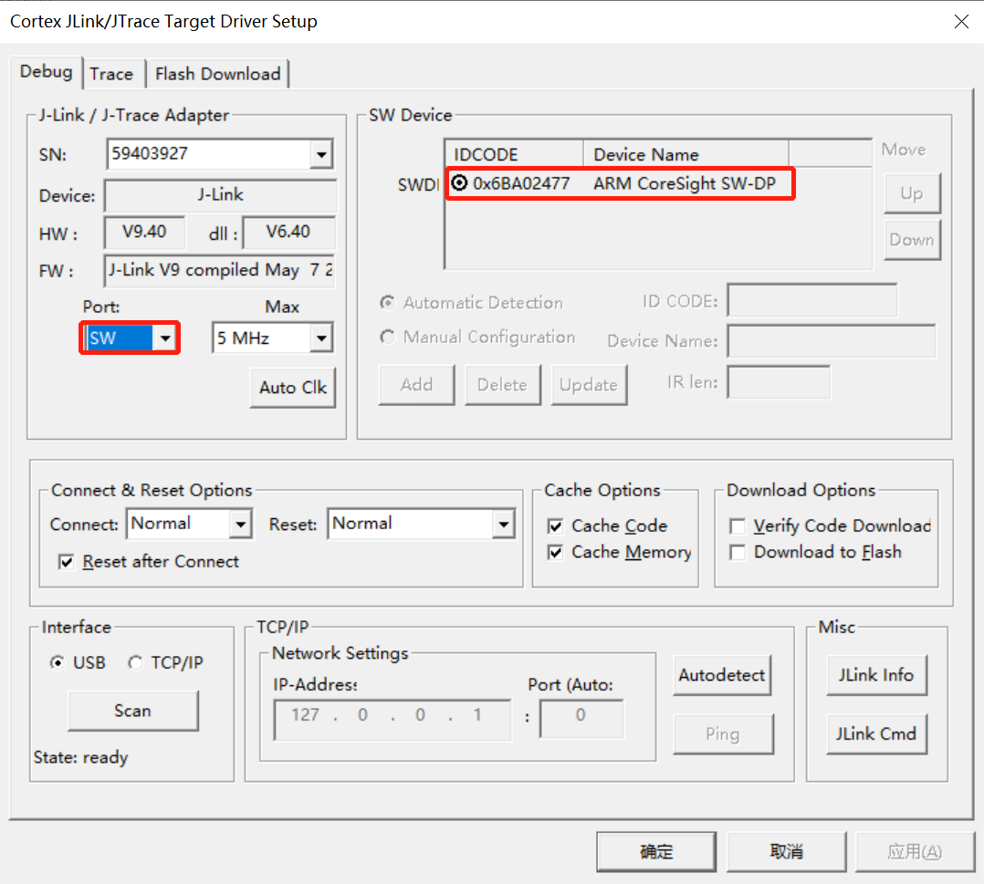
此时开发板MCU识别到JLink调试器,选择SW方式。
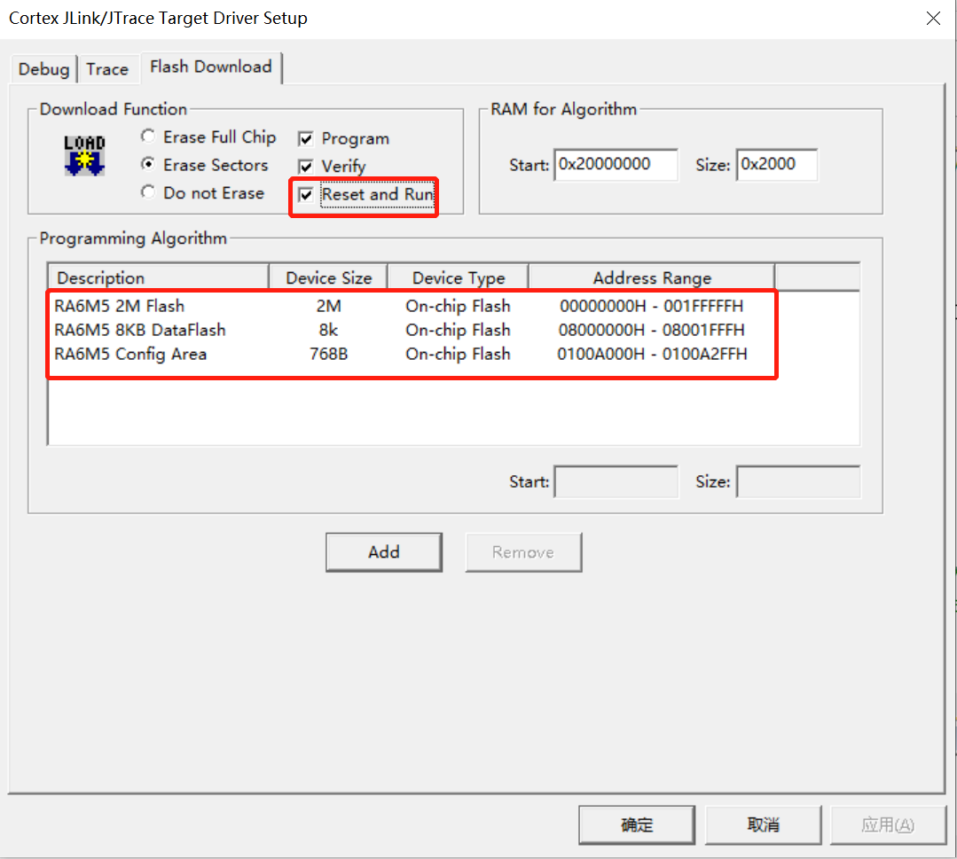
接下来添加关于板卡的下载算法,这里必须添加如下三个算法,否则会下载失败。
下载完成后,板卡上的LED1、LED2、LED3按如下图频率被点亮。此次评测就告一段落了,如有不同见解,欢迎留言回复 !咱们后会有期。 !咱们后会有期。

|
|